PCR-LE/LE2
Series can produce a DC output that enables you to test DC-powered devices such as DC-input converters. This article introduces the important precautions and useful functions to effectively operate PCR-LE/LE2 Series in DC mode.
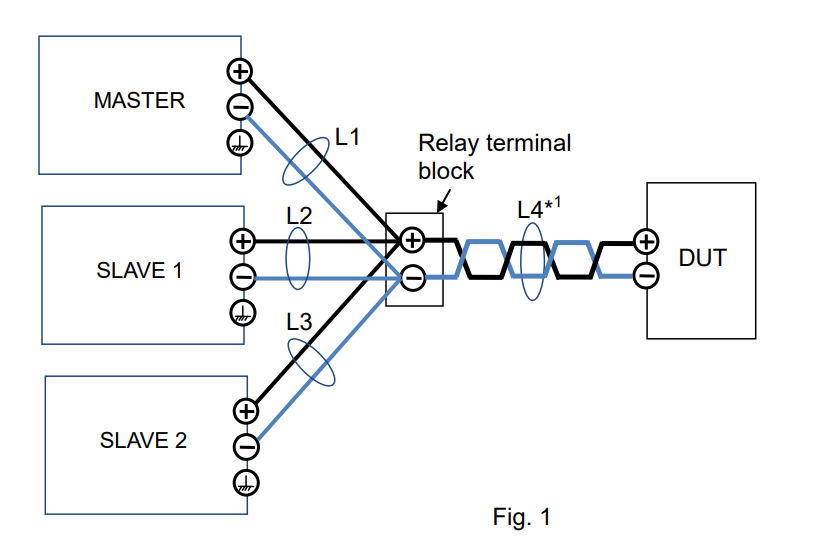
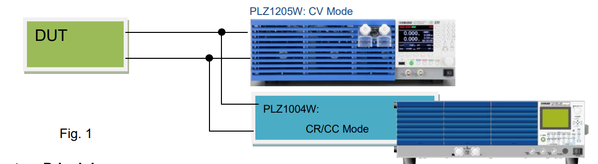
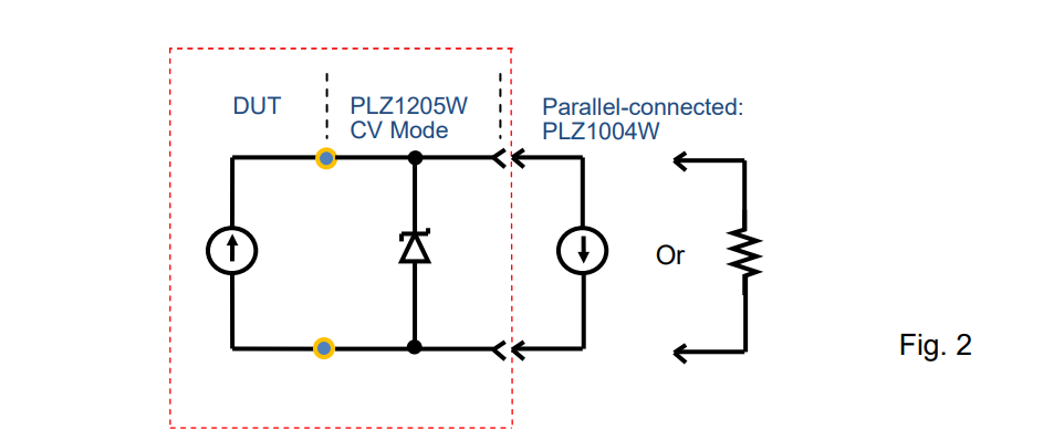
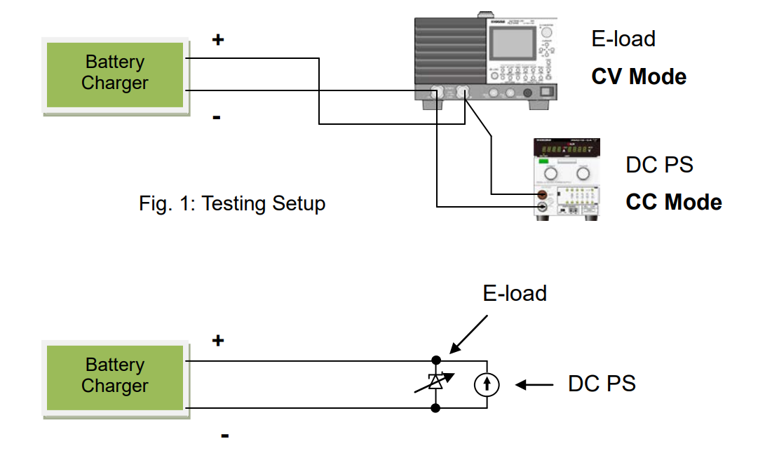
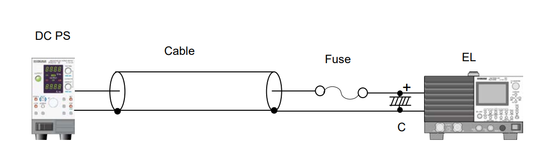
1. Circuit Model
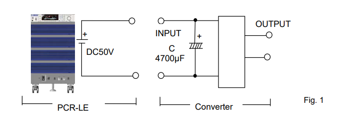
See Figure 1 for the test circuit model with PCR-LE. It illustrates the DC-input converter/inverter that has a capacitor-input circuit but without an inrush current prevention circuit.
2. Rated DC Current and Maximum Instantaneous Current
2-1 Rated DC Current for PCR6000LE
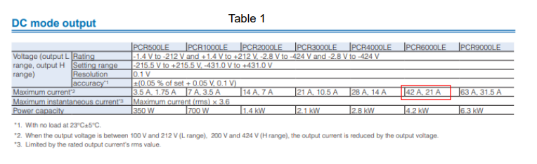
From Table 1;
DC input 200V: The rated DC current (maximum current) is 21A. The maximum instantaneous current, 3.6 times the rated DC current, is 75.6A.
DC input 100V: the rated DC current is 42A. The maximum instantaneous current is 151.2A. The rated DC current is 70% of the rated AC current.
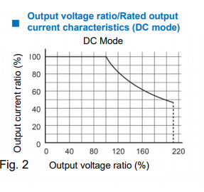
From Figure 2;
Example 1) If DC input is 100V and the output voltage is DC50V; the output voltage ratio is 50% → The output current ratio is 100% → The output current equals the rated DC current.
Example 2) If DC input is 200V and the output voltage is DC400V; the output voltage ratio is 200% → The output current is limited by 50% → The rated DC current is 10.5A and the maximum instantaneous current is 37.8A.
2-2 Maximum Instantaneous DC Current
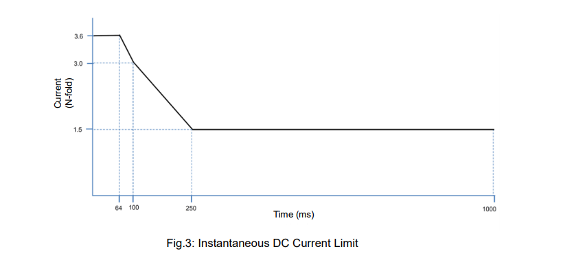
As stated above, the maximum instantaneous current is 3.6 times the rated DC current. The overcurrent protection (OCP) in PCR-LE activates when the output DC current exceeds the maximum instantaneous current. See Figure 3 for the DC current limit characteristics. DC current can remain within this limit. If the RMS DC current exceeds the limit for 1 second or more, the overload alarm is triggered to shut off the current.
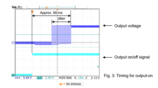
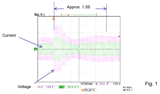
3. Inrush Current
The rise time of PCR-LE is less than approx. 80μs in any response setting. While large inrush current would flow to the model circuit shown in Figure 1, PCR-LE equipped the current limit circuit can hold the DC current level to the maximum instantaneous current. If the RMS DC current exceeds the limit for 1 second or more, the overload alarm is triggered to shut off the current. The alarm can be cancelled by pressing the ALARM CLR key.
To prevent such inrush current, the power supply capacity should be increased. In PCR-LE, you just turn Soft Start on to raise the output voltage gradually and limit the current through the capacitor. To set Soft Start, press OTHERS (SHIFT + MEMORY) > RISETIME (F1).
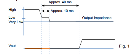
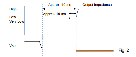
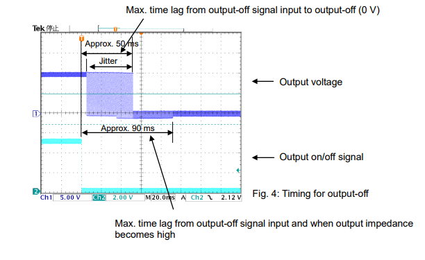
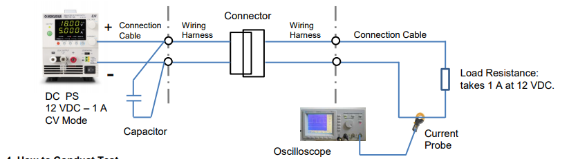
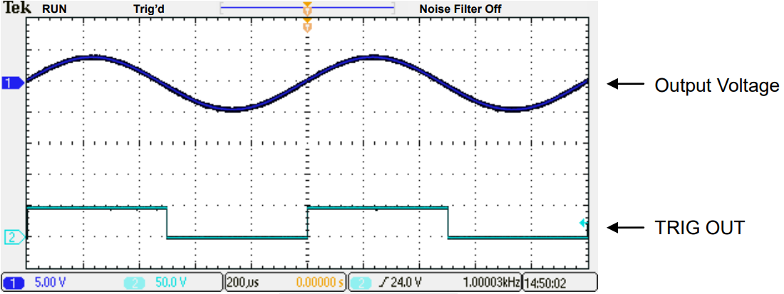
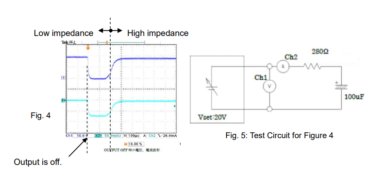
4. Impedance when output is off
When an output is turned off, PCR-LE has a high impedance as shown in Table 2 (approx. several kΩ to several tens kΩ). As shown in Figure 4, the voltage reaches 0V for approx. 200μs when the output is turned off, and then PCR-LE is in a high impedance state. During this 200μs, the capacitor in Figure 1 discharges its electric charge and the OCP activates to shut off the current.
Table 2: Impedance when output is off
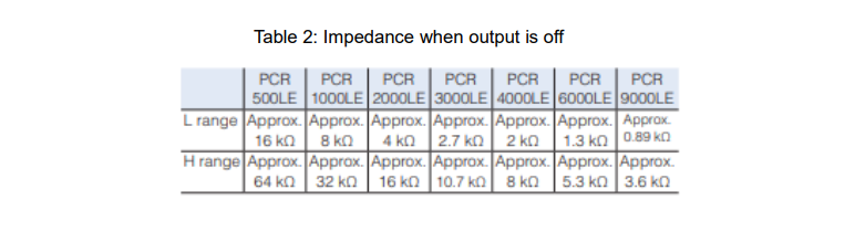
If you have any trouble during this 200μs, it is recommended that you insert a diode in series for the PCR-LE output or set COFIG > Surge Suppression > OFF to leave the high impedance (Voltage does not reach 0V). To set surge suppression, press CONFIG (SHIFT + OPR MODE) > 1/2 (F6) > SURGE S (F2) > OFF (F/W Ver.4.50 or later).
5. Others
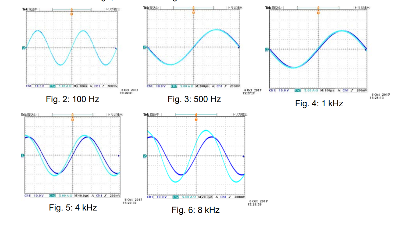
PCR-LE uses a high-speed amplifier. The output may become unstable due to capacitive loads or wiring conditions. With such loads, we recommend that you change the response setting to SLOW to keep stable operations.
To set the response, press OTHERS (SHIFT + MEMORY) > 1/3 > RESP.
Products Mentioned In This Article:
PCR-LE Series please see HERE


 FREE SHIPPING £75+
 CELEBRATING 50+ YEARS
 PRICE MATCH GUARANTEE