 FREE SHIPPING £75+
 CELEBRATING 50+ YEARS
 PRICE MATCH GUARANTEE


In this white paper, we are going to share the techniques to make the system that our bipolar power supply PBZ Series acts as a constant resistance load.
1. System Details
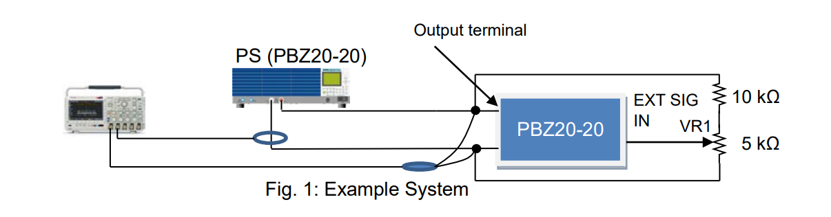
First, we are describing the system. See Figure 1 below; two units of PBZ20-20 are required for the system to operate as an AC electronic load ‘PBZ20-20’ and an AC power supply ‘PS (PBZ20-20)’:
1. CC mode is set on PBZ20-20.
2. The resistances are placed at the output terminal of PBZ20-20 to divide the voltage.
3. The divided voltage is applied via EXT SIG IN (BNC) to control the output current from PBZ20-20.
4. When the AC voltage is applied from PS, PBZ20-20 operates as a constant resistance load.
5. To adjust the current, connect a variable resistance (VR1) to EXT SIG IN.
2. Test Results
Next, let’s look at the test results on this system.
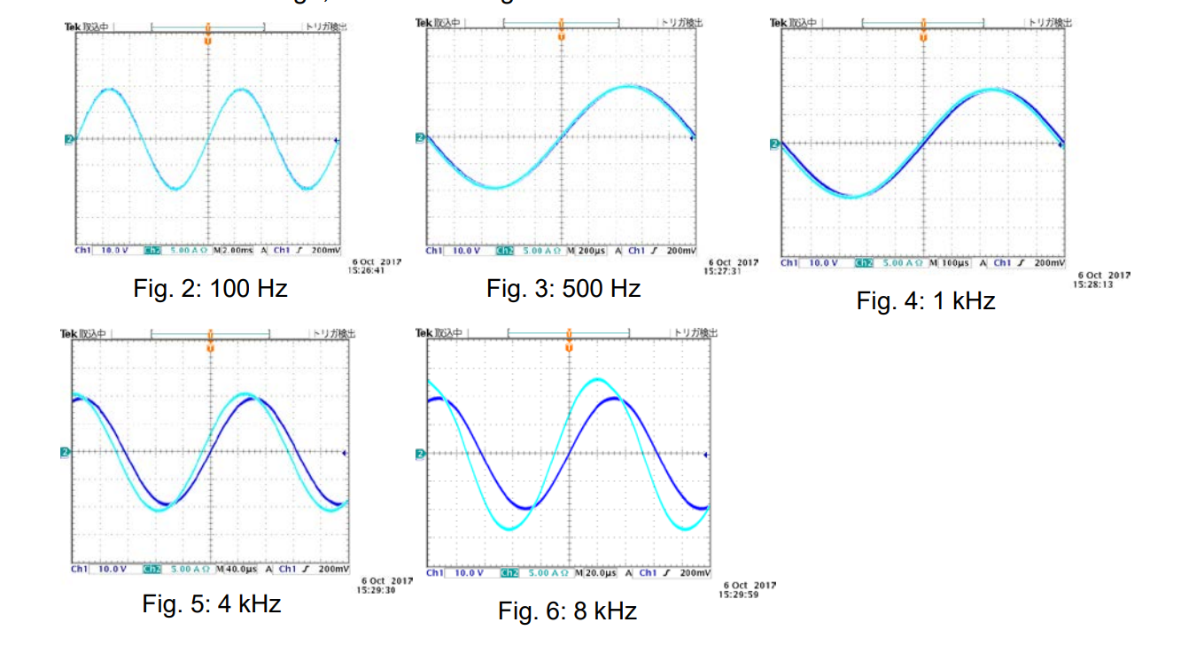
Given below are the phase relationships between the voltage and current under this system. Figure 2 – 6 show the input AC voltage waveforms and current waveforms:
Test Conditions: PS PBZ20-20: 40 VP-P, PBZ20-20: 40 AP-P specified by VR1 Waveform in blue: Voltage, Waveform in light blue: Current
3. Conclusion
As the frequency is getting higher, the current leads the voltage. This implies that PBZ20-20 operates like a capacitive load at the higher frequency in this system. When the sinewave frequency is 8 kHz (Fig. 6), the phase difference between the voltage and the current is approx. 28°. From this phase difference, the power factor will be 0.88.
Products Mentioned In This Article:
- PBZ Series please see HERE