 FREE SHIPPING £75+
 CELEBRATING 50+ YEARS
 PRICE MATCH GUARANTEE


Blown Fuse Testing Precautions When Using Electronic Load
This article will address some precautions on the blown fuse testing such as the unit testing or cable and fuse testing (see Figure 1) and fuse component testing.
1. Test System
A DC power supply, cable, fuse and electronic load are connected as shown in Figure 1.
1) Prepare a DC power supply whose current and voltage capacity are greater than a test range.
2) Set an electronic load to CC mode and set a test current from an electronic load panel.
3) DC power supply: Turn the output on. Electronic load: Turn the load on.
4) Monitor a current with an electronic load ammeter. In general, an electronic load ammeter is more accurate than that of power supply.
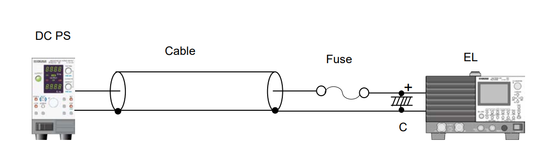
Fig. 1
2. Precautions
1) Cable inductance may cause oscillations on electronic loads, especially using longer cables. To prevent it, lower the response speed (RESPONSE) of electronic load (Example for PLZ-4W Series: set RESPONSE to 1/10).
2) If the oscillations persist longer even after lowering the response speed, place an electrolytic capacitor (C = approx. 1000μF) on input terminals of electronic load as shown in Figure 1.
3) Electronic loads can also dynamically change a current (E.g. 0.5A-5A, Duty: 30%, at 200HZ). The rise and fall times vary with the response setting and slew rate setting.
Products Mentioned In This Article:
Kikusui’s full range of DC Power Supplies and Electronic Loads please see HERE