Free Shipping logo FREE SHIPPING £75+
50 years of Telonic Instruments Ltd logo CELEBRATING 50+ YEARS
Price Match logo PRICE MATCH GUARANTEE

Necessity of Grounding Output Terminal for DC/AC Power Supply

Posted on: June 23rd, 2021 by Doug Lovell

Power supply has the following three output terminals:
– DC power supply: Positive/negative terminals and Ground (GND) terminal – AC power supply: L/N terminals and GND terminal.
Upon using both power supplies, it is necessary to determine whether either of positive or negative terminals or L/N terminals is connected to the GND terminal.
As our factory default;
– DC power supply: Depending on the series or models, the GND terminal is connected to the negative terminal or floating (non-grounding).
– AC power supply: The GND terminal is floating.
The following information may help you to ground the power supply properly.

1. Isolation Block Diagram for Each Terminal
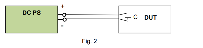
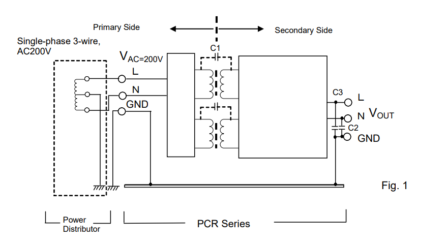
Figure 1 shows how the output (secondary) terminals of AC power supply are isolated from the input (primary) terminals and the GND terminal. The isolation block terminal for DC power supply can be compatible to Fig. 1.
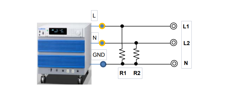
Figure 1 provides the example as: single-phase three-wire, AC200V.
1) The GND terminal at the output side is connected to the GND terminal at the input side. The GND terminal at the input side is required to be grounded by connecting to the ground terminal at the distribution board for safety reasons. If not, please make sure to check the condition of EUT.
2) The output terminals except for the GND terminal are isolated from the input terminals. Isolation is specified in specifications. E.g.) Withstand voltage between the primary and secondary side is AC1500V/1 mins.

2. Requirement and Effect on Grounding Output Terminal
The requirement and effect on grounding are described in each subsection with case studies.
2-1 Electric Shock Caused by Isolated Power Supply
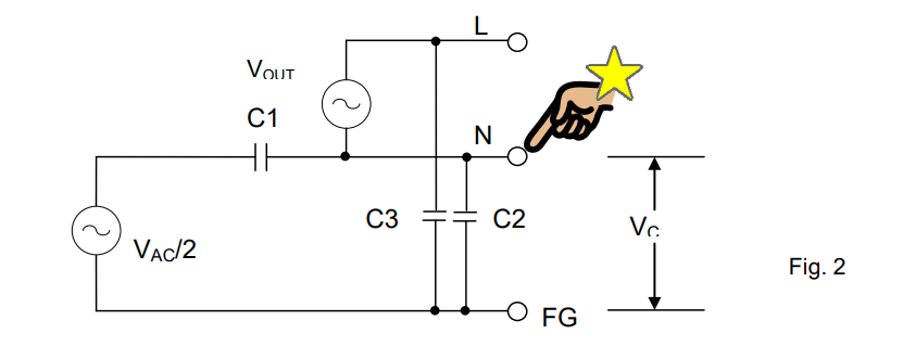
The following inquiry might be asked: ‘Why did I have an electric shock when I touched the N terminal even the AC power supply is isolated?’
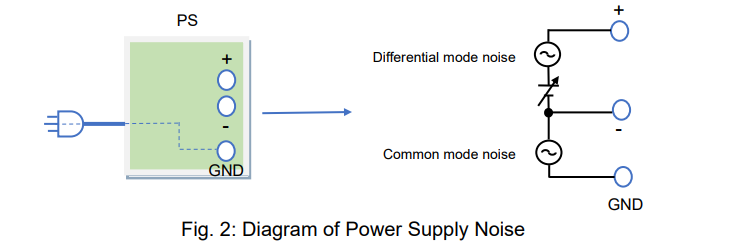
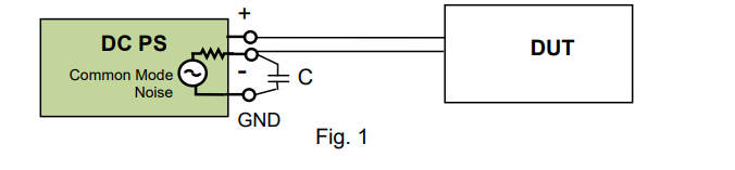
As shown in Figure 1 above, the primary and secondary terminals of power supply are isolated. However, Figure 2 shows that the voltage is divided at the capacitance of C1/C2 and applied to the N terminal. In this case, you may have an electric shock when touching the N terminal.
To avoid this issue, please connect the N terminal to the GND terminal or connect a high-capacity capacitor between the N terminal and the GND terminal.

2-2 Power Supply for Swimming Pool Water Treatment
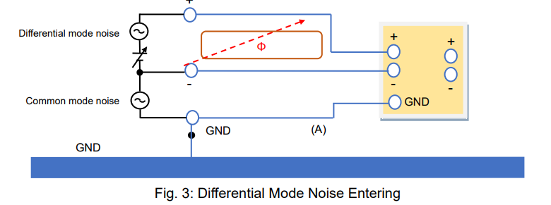
Figure 3 shows the equivalent circuit of the swimming pool water purification system. As you can see, the output from the DC power supply is in the swimming pool. If the isolation between the primary and secondary terminals is not fully secured due to any trouble, the voltage from the primary terminals will be applied into the water. Then, it induces the leakage current into the swimming pool and it may cause an electric shock.

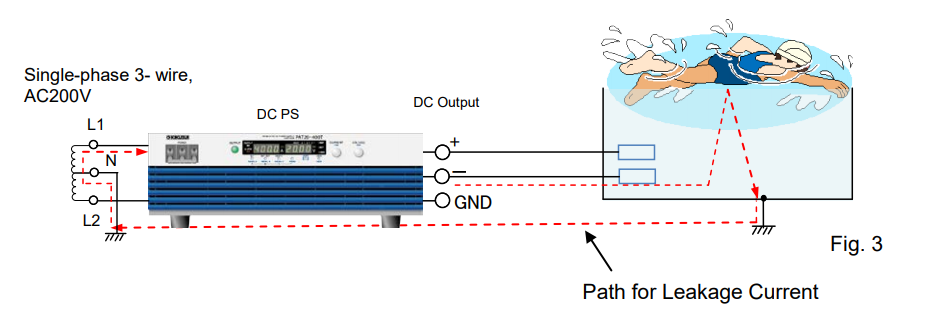
To avoid this issue, please always connect either of positive or negative output terminals to the GND terminal. For the case of 2-1 and 2-2, the grounding is required at the secondary terminals for safety.

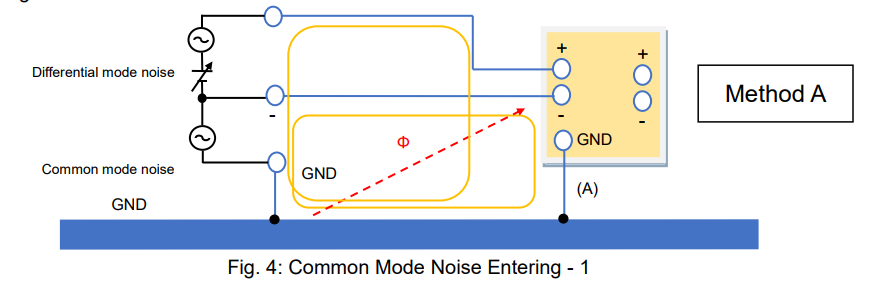
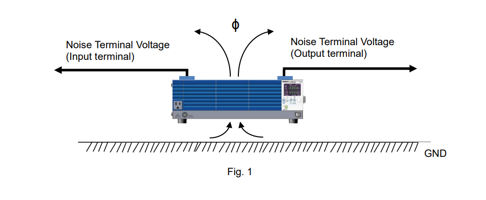
2-3 Power Supply for Wireless Transmitter (Ground Connection at High-Frequency)

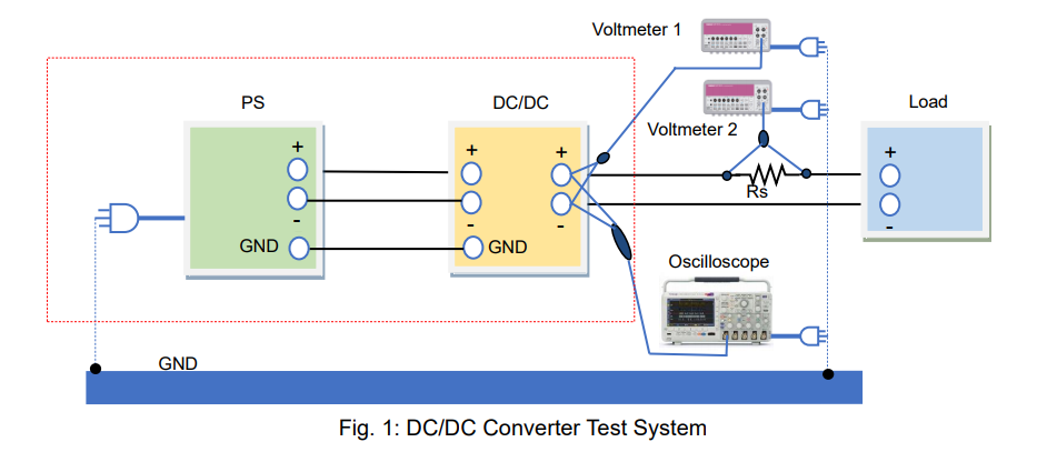
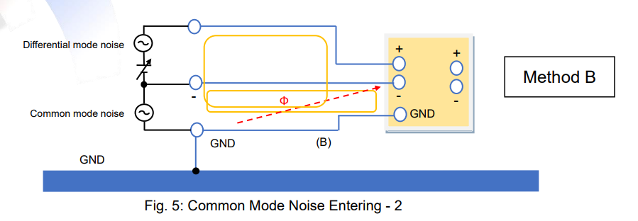
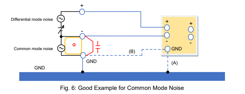
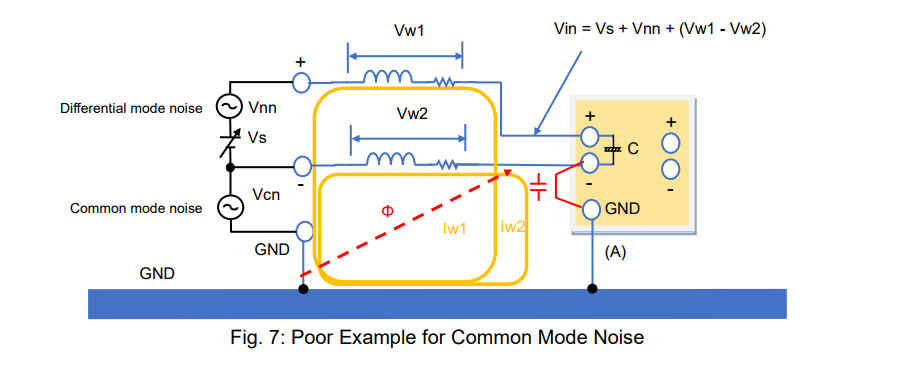
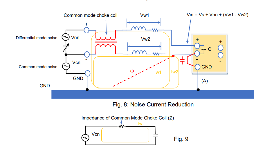
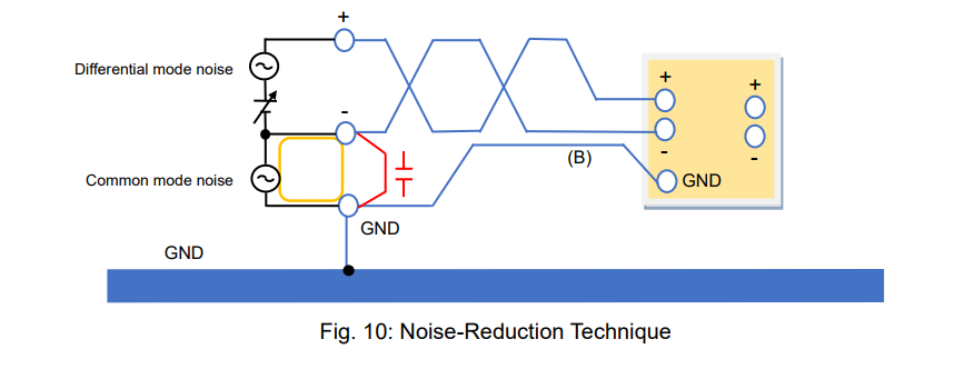
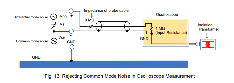
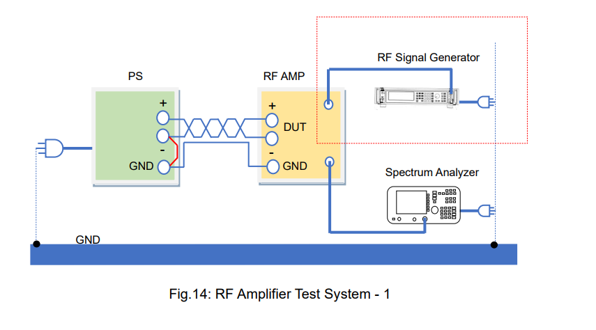
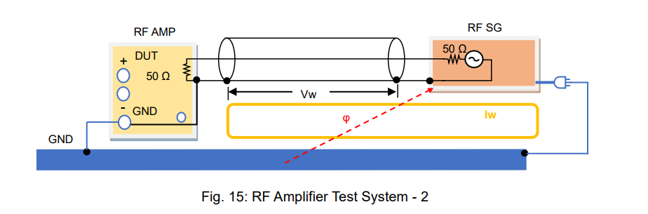
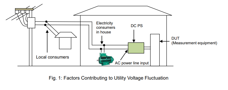
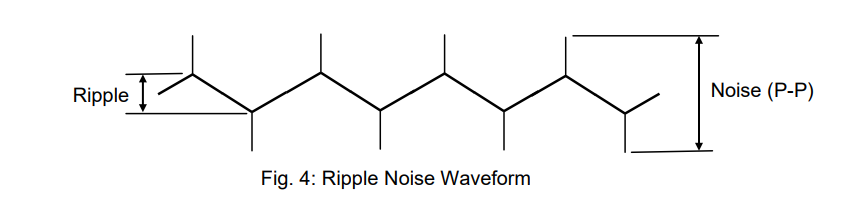
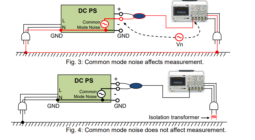
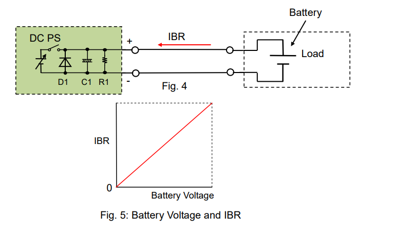
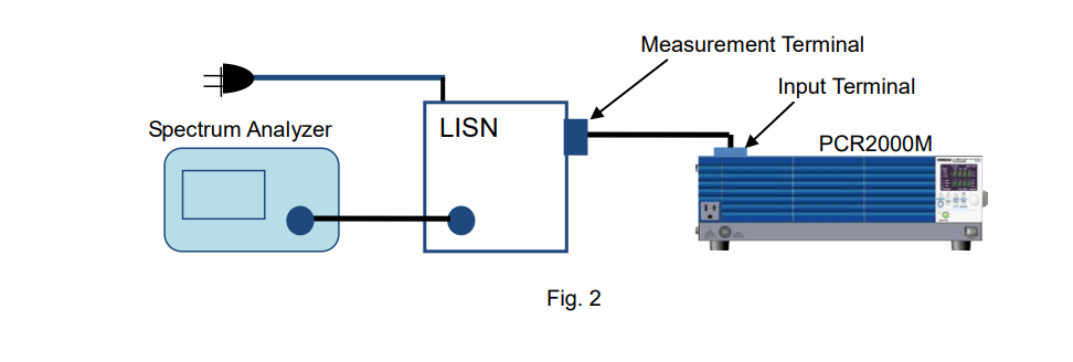
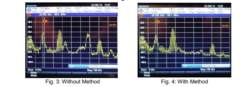
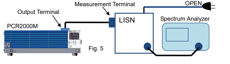
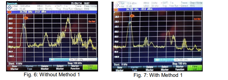
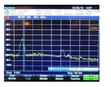
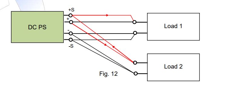
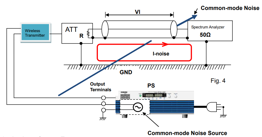
Figure 4 shows the system that measures the wireless transmitter power. Common-mode noise is generated inside the power supply. In this figure, the output terminals of power supply are connected to the wireless transmitter. Common-mode noise is emitted to the surroundings as shown by the arrow. When the common-mode noise passes through the ground loop, it turns to the current noise (I-noise). Then, when this current noise passes through the cable outer coating, VI will be generated and measured by the spectrum analyser.
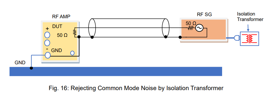
To avoid this issue, the output terminal of power supply is connected to the GND terminal to eliminate the common-mode noise.

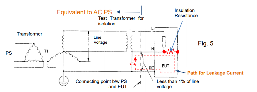
2-4 Leakage Current Test
Figure 5 is referred to the IEC60990 that defines the measurement of leakage current (protective conductor current and touch current). This circuit is equivalent to the measuring of the leakage current when the AC power supply is connected to EUT. In this case, the N terminal should be connected to PE (Protective Earthing = GND terminal) to create the path for leakage current as shown by the red dotted lines.
Since either of output terminals should be grounded to measure the leakage current, AC power supply is suitable for such measurement.

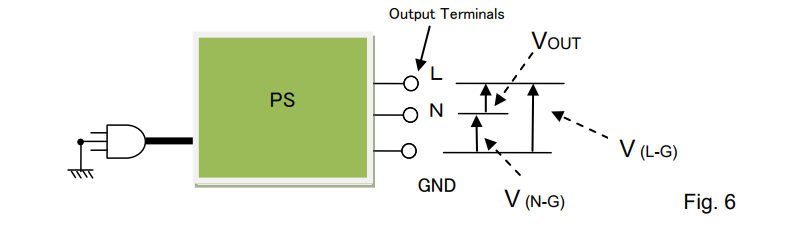
3. Consideration for Voltage to Ground
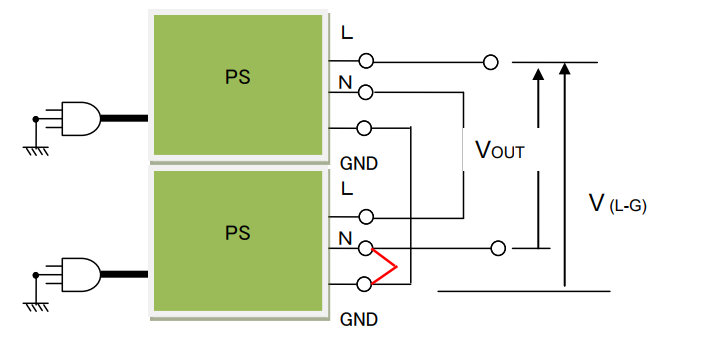
Voltage to ground is specified for output terminals by product series/models. It means the maximum voltage to be applied between the output terminals (positive/negative or L/N) and GND terminal (chassis potential). In Figure 6, neither V (N-G) nor V (L-G) can exceed the voltage to ground.
For the figures below, if you use the DC power supply, please regard L terminal as positive terminal and N terminal as negative terminal.

Please be noted that the output voltage applied to the output terminals and GND terminal might be limited depending on the power supply specification.
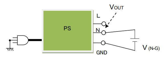
Two examples are listed below with the condition as: Using DC power supply with Rated output voltage= DC300V and Voltage to ground=±DC500V.
Example 1: If DC250V is applied between N and GND, the output voltage (VOUT) is limited to DC250V.
VOUT = Voltage to ground – V (N-G) = 500V – 250V = 250V

Example 2: Two DC power supplies are connected in series and the N terminal and GND terminal at the second power supply are connected. V (L-G) is DC500V so that the VOUT is limited to DC500V even with two power supplies used.

How to Minimise Power Supply Noise in Test Systems

Posted on: June 23rd, 2021 by Doug Lovell

Noise is an unwanted but inevitable problem in test systems including power supply sources, except batteries, which are low-noise power sources. Some amount of noise is always generated or relayed by power supplies; however, a power supply is a device that supplies power to another device, and not intended to be used by itself. Power supply noise should be low enough so as not to interfere with the neighbouring equipment or test results.
This white paper will discuss how to mitigate the power supply noise in the test systems, showing two test system examples – a DC/DC converter test system and an RF amplifier test system. It particularly explains how to setup the power supply or measurement equipment in the test system, including the wiring method.

1. Power Supply Noise in DC/DC Converter Test Systems
Figure 1 shows the test system. The DUT is a DC/DC converter powered by a power supply with a load resistor connected. An oscilloscope measures the output voltage ripple of the DC/DC converter; voltmeter 1 measures the output voltage; the output current can be taken by measuring the voltage across the shunt resistor from voltmeter 2. The input source of the power supply, oscilloscope, voltmeter 1 and 2 are grounded to the GND for safety.

1-1. What is Power Supply Noise?
Power supply noise can be divided into two types: “common mode noise” generated in a ground loop and “differential (normal) mode noise” appearing in the positive and negative lines. The common mode noise is applied on the ground (GND) line and negative line. The GND terminal is grounded when the power cable is plugged into an outlet.

1-2. How to Minimise Power Supply Noise
This section explains how differential mode noise and common mode noise enter a system and how these noises can be reduced.
1) How Differential (Normal) Mode Noise Enters DUTs
The positive and negative cable wiring deliver the differential mode noise to your DUT. How the DUTs reject the noise depends on their power supply rejection ratios (PSRR). The DUT’s tolerance against the differential mode noise can be measured by determining how the noise frequency characteristics affect the outputs of DUTs. For reducing noise, using cable inductance and placing a capacitor with good high-frequency characteristics at the input of your DUT may help. With a wire loop, magnetic flux may be generated due to the differential mode current as shown in figure 3. This noise is emitted into the air, affecting the neighbouring equipment. To suppress this noise emission, twist the positive and negative cables.

2) How Common Mode Noise Enters DUTs
Common mode noise appears in the positive and negative lines of the power supply carried through the GND contact (common ground). That is to say, common mode noise enters both the GND and negative line. The same amount of common mode noise (voltage) also appears in the positive line, where the differential mode noise (voltage) and DC voltage are applied.
When the common mode noise enters the DUT, it may be converted to the differential mode noise depending on the stray capacitance between the signal line and GND line of the DUT, and this can affect the output performance of the DUT. If there is a large ground loop and wire loop, a magnetic flux may be generated due to the noise current as shown in figure 4, and this noise is emitted into the air, affecting the neighbouring equipment (e.g. measuring devices). To reduce this noise, make the loop smaller. It can be done by grounding the DUT’s GND by following method ‘B’ in figure 5.

3) Good Defense for Common Mode Noise
In both cases shown in figure 4 and 5 (method ‘A’ and ‘B’), the ground loop is present, so common mode noise and magnetic flux are unavoidable. To prevent common mode noise emission, add a capacitor or short wire between the GND and negative terminals of the power supply as shown in figure 6.

4) Poor Defense for Common Mode Noise
Figure 7 shows an example similar to figure 6: a capacitor or short wire is added between the GND and negative terminals at the input of the DUT. It appears good, but noise currents Iw1 and Iw2 increase, and the magnetic flux becomes stronger than those of figure 4 and figure 5. This causes an electric wave, which can interfere with measuring systems and other neighbouring equipment. It also assists the generation of the differential mode noise (Vw1 – Vw2) due to the difference of the wire impedance.

5) Common Mode Choke Coil
In the case of figure 7, if the noise current reduces, the magnetic flux noise can also decrease. In figure 8, after adding a common mode choke coil, the cable impedance on the wire loop will increase. Accordingly, Iw1 and Iw2 will reduce. The common mode choke coil can also block external noise (magnetic flux) so that it can be added in the system example shown in figure 6. Figure 9 shows the relationship between the impedance of the common mode choke coil (Z) and Iw. If Z increases, Iw decreases. As a result, the magnetic flux will decrease.

6) Power Supply Noise-Reduction Technique
Now, let’s summarise how to control the power supply noise. Figure 10 shows one example of a reduced-noise test system. If the noise persists on your test system, try the following:
A) Twist the output cables of the power supply. *1
B) Connect the output terminal of the power supply to the GND or connect them with a capacitor.
C) Avoid the ground loop.
*1: It is also effective to apply a common mode choke coil to the power supply output.

1-3. Power Supply Noise in Measurement Equipment
Figure 11 shows the noise-controlled test system. The DUT is a DC/DC converter. However, even with such system, the power supply noise cannot be fully suppressed. Furthermore, the DC/DC converter inevitably generates noise as well. The DC/DC converter noise can be also classified as differential mode noise and common mode noise.
The test instruments have notable characteristics. The voltmeters are isolated from the power supply’s GND, but the oscilloscope’s GND is connected to it.
This section explains how the common mode noise affects oscilloscope measurements and how to handle it.

1) How Common Mode Noise Affects Oscilloscope Measurements
Figure 12 shows that the DC/DC converter is measured with the oscilloscope at its input terminal. In the ground loop, the common mode noise voltage (Vcn) appears, and the noise current (Iw2) circulates through the outer conductor of the probe cable. Then noise voltage (Vw2) is generated between the negative terminal of the DC/DC converter and the oscilloscope’s GND. Consequently, the voltage measurement is calculated as Vs + Vnn + Vw2. It is affected by the common mode noise.
The input impedance of the oscilloscope probe is 10 MΩ as shown below, so Iw1 caused by Vcn cannot flow through the center conductor of the probe cable. Accordingly, no noise voltage generates due to Iw1. Only Vw2 is included in the measurements.

2. Power Supply Noise in RF Amplifier Test Systems
Figure 14 shows a noise-controlled test system. The DUT is an RF amplifier. The RF signal from the RF signal generator is amplified by the RF amplifier. The output of the RF amplifier is measured by a spectrum analyser. RF amplifiers are small signal-tuned amplifiers that amplify small signals at radio frequencies. The chassis of RF amplifiers is at GND potential. Therefore, an external magnetic flux caused by the common mode noise should be removed from RF amplifier measurements.
The magnetic flux can be generated around the output of the power supply as well as from the chassis or power supply line.
This section explains how the external magnetic flux affects the RF amplifier measurements and how to handle the noise.

1) Why External Magnetic Flux Affects RF Signals
Figure 15 shows that the RF signal generator output connector is connected to the RF amplifier input port by a coaxial cable. In this system, the ground loop is obviously formed, so if an external magnetic flux caused by common mode noise passes through this loop, the noise current (Iw) flows through the outer conductor of the coaxial cable. Thus, this generates the noise voltage (Vw). Vw is added to the RFSG output through the input port of the RF amplifier. The RF coaxial cable has an impedance of 100 Ω in total at its center conductor. As an external magnetic flux passes this loop, the current does not flow through the center conductor with high impedance, so that the noise current (Iw) only flows through the outer conductor of the coaxial cable. These unbalanced currents lead to adding Vw to the RF signals.

2) How to Minimise Common Mode Noise
The above noise issue is caused by the ground loop. To solve it, break the ground loop by placing an isolation transformer as shown in figure 16 (see also Sec. 1-3-2 above).

Another solution is to wind the coaxial cable on a toroidal core, which blocks the current from flowing through the outer conductor of the coaxial cable.

Products Mentioned In This Article:

Full range of Kikusui products please see HERE

DC Electronic Load – Part 2: Basic Operation Mode and Principle (1)

Posted on: June 23rd, 2021 by Doug Lovell

As described in Part 1, electronic loads can act as a variable resistor and regulate a current depending on your applications. With this function, electronic loads can be used as substitute for high-power components. To fulfill this function and test DUTs effectively, there are four operation modes for electronic loads: 1) constant current 2) constant resistance 3) constant voltage and 4) constant power. Part 2 and Part 3 will describe each of these modes and the sequence function to simulate the specific electric and electronic components.
2-1. Constant Current (CC) Mode
In CC mode, an electronic load consumes constant current in regardless of input voltage variations. Figure 2-1 shows the connection diagram between the DC power supply and electronic load. Figure 2-2 shows the input current – input voltage characteristics in CC mode. You can see that the current is constant all throughout despite changes in voltage.

For example, if your test power supply has the output voltage variable range of 10 V ± 1 V, and its rated output current is 1 A, you need to determine whether it can provide 1 A with its output voltage change from 9 to 11 V. So you should prepare an electronic load that constantly consumes the current of 1 A regardless of the input voltage changes from 9 to 11 V.
Figure 2-3 shows the connection diagram. Figure 2-4 shows that the electronic load operates the CC mode regardless of the input voltage changes from 9 to 11 V.

You can also let the electronic load behave as a variable resistor (see also Part 1, Sec. 1-2-1: “Act as Variable Resistor”) but you will need to change the resistance value of the electronic load each time the input voltage changes. This is not efficient because you need to set the resistance and monitor the current all the time. Figure 2-6 shows that the electronic load consumes the current of 1 A by varying the resistance value.

Compared to this method, the CC mode allows you to easily vary the current to flow. The CC operation is intuitive and used for diverse applications.
By the way, what is an operating principle of the CC mode? As stated in Part 1, electronic loads can provide various operations depending on the circuit functions. In CC mode, electronic loads will automatically adjust the resistance value, just like the way of Figure 2-6, to maintain the constant current. In more detail, electronic loads will monitor the current; when the voltage rises, it increases the resistance with reducing the current flow, and vice versa, when the voltage falls, it decreases the resistance to prevent the current from falling.
Operating Principle
Figure 2-7 shows the operating principle diagram of the CC mode. The error amplifier internally controls the current regulator (equivalent to the resistance value) that compares the set current (I) and actual input current detected by the current detector to make them equal. So, the electronic load can constantly absorb the set current (I) by using the feedback control, which is quite popular method in power supplies.

The current regulator in Figure 2-7 controls the current flow. The electronic load circuits have elements such as a transistor or FET rather than a resistance element (see figure 2-6), because they are more electronically easy to control. Figure 2-8 shows the circuit diagram example of the CC mode. In the circuit, the operational amplifier controls the power transistor to make the voltage across the current sense resistor equal to the voltage reference for current setting, so that this circuit enables the CC mode.
The voltage is applied to the electronic load to sink the current. This applied energy is transformed into a heat by the power transistor or power FET so the electronic loads often have a cooling fan.

Example Applications for CC Mode – Electric Wire Heat Test and Fuse Melting Test

As a part of the power supply testing, a load regulation test and line regulation test will be performed by the CC mode of electronic loads. During these tests, the output voltage from the power supply will vary within its maximum ratings so the CC mode is suitable for these tests. The other example applications for the line regulation test (CV test) are an electric wire heat test (fig. 2-9) and a fuse melting test (fig. 2-10). The wire resistance and fuse resistance will change significantly when the current flows through them. To sink a constant current from the test samples, use the CC mode of electronic loads.

2-2. Constant Resistance (CR) Mode
The CR mode is a mode that electronic load act as a base component, variable resistor (see also Part 1, Sec. 1-2-1: “Act as Variable Resistor”). When an electronic load has a resistance characteristic like figure 2-11 and 2-12, it operates in CR mode. As shown in figure 2-12, you can adjust the resistance value such as 1 Ω or 3 Ω during the CR mode.

The CR mode is suitable for various applications. It is useful that electronic loads act as a large-capacity variable resistor. One of the typical applications is to test the current limiting characteristic of DC power supplies.
Figure 2-13 shows the connection diagram between the DC power supply and electronic load. The blue straight line in figure 2-14 shows the range that the power supply operates in CV mode. Point ‘a’ shows that the input voltage of electronic load is 50 V with the resistance of 3 Ω. The input voltage moves along this blue line in according with the resistance variations. If the resistance decreases and the input voltage will reach point ‘b’, then the voltage moves along the red line. When the resistance turns to 1 Ω, the input voltage will reach point ‘c’. While the input current is on the red line, the output current from power supply is regulated by 25 A.

The CR mode is also constructed in the circuit functions of electronic loads. The resistance (R) is calculated by R = V/I. In figure 2-14, the resistance is the slopes.

Operating Principle
Figure 2-15 shows the operating principle diagram of the CR mode. The left side of the diagram is the same as shown in figure 2-7 and the right side shows the component to be used for the CR mode. The multiplier will multiply the input voltage (V) by the reciprocal of set reference (1/R), so the multiplier will output V/R. It equals to ‘V/R = I’, so when V is applied the current will flow according to ‘I = V/R’. That is, the set reference R (= V/I) is constant and this circuit operates in CR mode based on R. The figure below uses the reciprocal of set resistance (1/R), so you adjust it by R. 1/R is conductance G (in Siemens S).
For the current regulator, a power transistor or power FET are usually used.

Example Applications for CR Mode – Switch Life Test
The example application for the CR mode is the switch life test. Figure 2-16 shows the test system that the switch is placed between the DC power supply and electronic load to repeat the on-off switching tests. Excellent test-reproducibility can be achieved from this system because the CR operation avoids the rapid current on-off switching.
(Note: The current rise time differs depending on the electronic load performance.)

Products Mentioned In This Article:

  • Kikusui Electronic Loads please see HERE

What Makes a Good Power Supply?

Posted on: June 23rd, 2021 by Doug Lovell

DC or AC regulated power supplies (hereinafter called ‘power supply’) can be classified into eight types and four categories in accordance with the output source (DC or AC), output range, polarity or circuit method as shown in Table 1.

In this white paper, we look at four characteristics associated with the power supply’s specification: line regulation, load regulation, transient response and ripple noise. We also discuss how to determine the ability of the power supply by these four characteristics. Note: This white paper refers to the constant voltage characteristics based on an AC line input.
1. Line Regulation
Firstly, here’s how electricity gets to your power supply: 1) Power plants generate electricity. 2) Electricity travels via a power grid. 3) Electricity is distributed by a circuit breaker at your home or office. The circuit breaker is connected to each of electrical outlets by wiring. 4) Finally, electricity travels through these wires to the outlets where your power supply is plugged in.
See Figure 1 below: if some electricity consumers on the same distribution line consume large electric power, the utility voltage drops, and vice versa, if they consume less power, the utility voltage rises. A good power supply can keep its output voltage stable despite the utility AC voltage fluctuation.

Line regulation is changed in power supply output voltage due to variation of input line voltage. It is expressed as an actual change value in the output voltage relative to the ±10% change in the input line voltage (The standard input line voltage is: 120 Vac in U.S.A and 100 Vac in Japan). For industrial power supplies, the change in the input line voltage may be defined as ±15%. The input voltage at which the power supply is designed to work (such as the standard voltage ±10% or ±15% as above) is the rated input voltage.
The performance specification for the power supply is ensured within the rated input voltage. Some power supplies define a wide rated input voltage range under the specific line regulation. In general, a good power supply has small line regulation but it is difficult to develop.

*1: Variation of input voltage: 85 Vac – 135 Vac or 170 Vac – 265 Vac

2. Load Regulation
A load on an electrical system is any device, part or portion of a circuit to which power is drawn from a power supply. So, how do you find which power supply can deliver enough current to your load? To choose an appropriate power supply to your load, check the rated output current, maximum load current that a power supply can provide, specified on its product data sheet. Furthermore, in fact the load current is affected by the load variation.
If the output voltage of your power supply significantly changes with the load variation: ● Your load may be damaged due to an unstable output voltage.
● Test data reliability or test reproducibility cannot be ensured due to the test voltage variation. Load regulation measures how much the output voltage is affected by the load variation from 0 to 100% (no load to full load).
A good power supply has small load regulation.

3. Transient Response
For example, the load regulation can be measured by the formula:
‘output voltage value after keeping a no-load state for 10 seconds’ – ‘output voltage value after keeping a full-load state for 10 seconds’.
This formula indicates that: ‘No-load voltage under a stable output voltage’ – ‘Full-load voltage’. The output voltage dynamically fluctuates while in the load current variation such as when a load is switched from no-load state to full-load state and vice versa. Transient response is the response characteristic how a power supply responds to a sudden load variation, that is, the time until an output voltage reaches a steady-state.
Note: Some power supplies define a no-load voltage as 10-plus % of a full-load voltage.

It is important how fast a power supply returns back to a steady-state. In other words, a good power supply has an excellent transient response time.
A power supply should provide a faster enough transient response to a load, otherwise a load current fluctuates before an output voltage returns to a steady-state and an output voltage becomes unstable.
See Table 4 for the reference value of the transient response time for each category of power supply.

4. Ripple Noise
A power supply consists of several components such as a power electronics circuit that converts a utility AC to a stable DC/AC output. To provide a stable voltage output, a power supply performs a negative feedback control; however ripple noise can be prevalent during this negative feedback operation. Figure 4 shows the typical waveform for ripple & noise generated from a power supply.

If your power supply generates a ripple noise, it will be superimposed on your DUT’s output voltage.
Especially with a high ripple noise, the following malfunctions may occur to your DUT:
A) If your DUT has a digital circuit:
● An input voltage for your DUT exceeds its threshold level and it may cause a malfunction on the digital circuit of your DUT.
B) If your DUT has an analogue circuit:
● Ripple noise is superimposed on your DUT’s output and it may reduce the quality of your DUT’s analogue signal.
Ideally, a good power supply has little ripple. In practice, however, you will purchase a power supply within a reasonably low-price range unless above malfunctions have been discovered. So, you may need to reduce the ripple noise depending on your power supply in use. If you want to know how to reduce the ripple noise, read the appendix below.
The higher the rated output voltage, the higher the ripple noise is provided by the power supply. Table 5 shows the typical ripple noise value according to the power supply category. Some power supplies may give the rms value and peak-to-peak (P-P) value of the ripple noise.

*3: If a linear-amplifier power supply incorporates a switching regulator, a ripple noise may increase. A lower ripple noise may be achieved by high-speed bipolar DC power supply.
*4: Measurement frequency bandwidth: 10 Hz to 1 MHz

Appendix: How to Reduce Ripple Noise from Power Supply
1. How to Reduce Ripple Noise
1) Connect negative output terminal of power supply to ground
Connect a negative output terminal and a ground terminal to minimize a high frequency common mode noise generated between both terminals. Figure 1 shows that a capacitor is placed between both terminals. If your DUT is accepted, connect both terminals by a conducting wire.

2) Place capacitor at feeding point of DUT
Place a capacitor (approx. 0.1 µF – 1 µF) at a feeding point of your DUT to reduce a high frequency common mode noise. This method is effective when the wiring distance from a power supply to a DUT is long.

2. Precautions for Ripple Noise Measurement
When an rms value is measured by a true rms meter or a noise is measured by an oscilloscope, place an isolation transformer between the true rms meter or oscilloscope and the power source line as shown in Figure 4. The isolation transformer eliminates a high frequency common mode noise to minimize measurement errors.
As shown by the red line in Figure 3, the common mode noise current is generated from the DC power supply and passes through the ground and returns to the power supply line. If the current flows through the probe cable jacket of the oscilloscope, the voltage Vn is generated and added to the measurement. The isolation transformer can eliminate this voltage Vn.

Products Mentioned In This Article:

  • Kikusui AC Power Supplies please see HERE
  • Kikusui DC Power Supplies please see HERE

What It Takes to Keep Regulated DC Power Supply Stable Part 2: Load Conditions

Posted on: June 23rd, 2021 by Doug Lovell

Basically, a regulated DC power supply (referred as DC power supply) is an electrical device that provides a constant output voltage; however, sometimes it cannot remain stable. There might be some factors that affect the stability of the DC power supply, and Part 1 previously focused on one of them: how you connect cables on a system. Here in Part 2, we look at one other important factor that needs to be considered: load conditions. Ensuring that your system runs smoothly may rely on the characteristics or state of your load.
In this white paper, we help you understand the typical issues involved with load conditions and how to solve them, particularly focusing on three types of loads: 1) inductive load 2) capacitive load such as battery and 3) regenerative load one by one.
1. If you use inductive load
An inductive load such as a coil of wire is a passive element designed to store energy. When a current flows through it, electromagnetic energy gets stored. This stored energy is released creating reverse current right after its power source is disconnected. Without any protection, an inductive voltage spike, which is always opposite polarity, is seen across the inductive load when its supply current is suddenly interrupted.
See Figure 1 below. As an inductive kickback protection, usually a diode (‘D1’) or equivalent diode in a low-impedance state is placed in parallel with output terminals of a DC power supply. When the output is turned off, D1 can make a path for an inductive current (‘IL’) to suppress an inductive kickback, and thus D1 can protect the DC power supply.
Meanwhile no big noise occurs. This is because; 1) The output-off speed is slow at a microseconds-order interval. 2) IL through D1 never exceeds the current through the inductance in the load. 3) The current for this system can keep the small variations.
Particularly, D1 is so-called a flyback diode.

As shown in Figure 2, if another switch is placed to control the DC power supply’s output, there is no longer any path for IL so that a reversed voltage spike is induced when an output is turned off. As for the switching on/off speed, it is quite fast and the fastest one will be 1 µs or less. If a supply current is suddenly interrupted at this speed, an induced voltage across the inductance (‘L’) will become significantly higher as calculating: ‘V = L x dI/dt’.
As you can see below, a stray capacitance creates a loop for this high-frequency high voltage and a load wiring acts like an antenna to generate an EM noise. Once the noise enters into the DC power supply or any other devices in the system, it may deteriorate their performance or cause malfunction.

To reduce the noise, place a diode (‘D2’) close to the inductance as shown in Figure 3 to let IL flow through D2.

2. If you use capacitive load such as battery

2-1 Place diode in series
When charging a rechargeable battery, we should take care of a potential difference between a supply voltage and battery voltage. If the supply voltage is lower than the battery voltage, a power source such as a DC power supply acts like its output is turned off, and then the output voltage becomes equal to the battery voltage.
Usually, the DC power supply equips a bleeder circuit (‘R1’ in Figure 4) that let a battery discharging current (‘IBR’) flow through R1. Once IBR flows through RI, the battery will get discharged. Figure 5 shows that IBR is linearly proportional to the battery voltage.
If the output is kept to be turned off or the supply voltage is always lower than the battery voltage, the battery will be fully discharged.

To block IBR, place a diode (‘D2’) in series as shown in Figure 6.

2-2 Remote sensing function
Battery charging is generally done with constant current constant voltage (CC-CV) method. In this mode, a battery is initially charged in CC mode until a battery voltage reaches a certain charging level, and then the charging process is switched to CV mode. This is to ensure that the voltage across the battery terminals does not exceed the maximum rated voltage of the battery while keeping the battery fully charged.
While in CC-CV mode, and a remote sensing function is turned on, you may want to put a remote sensing point at the battery terminals as shown in Figure 7. If so, the output voltage will fluctuate and worse still, the battery may be discharged through the sensing cable. This happens because a non-linear control is given by D2 or a voltage drop may occur with D2 at the battery terminals and it cannot be fully offset by the remote sensing function.

To avoid this, move the sensing point in front of D2 as shown in Figure 8. This can ensure that the DC power supply maintains the stable output. However, you should take care of the voltage drop caused by D2.

If you do not want D2 but want to use the sensing function, place a switch (SW1) on the sensing wiring (See Figure 9) to simultaneously turn on/off the both switches. In this case, when the DC power supply has the same voltage as the battery, turn SW1 on. To maximize the system efficiency, it is important to minimize the variations from the battery charging current and battery reverse (discharging) current.

3. If you use regenerative load
3-1 Sink current capability by DC power supply
The bleeder circuit (R1) in a DC power supply can absorb a current, typically by several percent of its rated output current*.
If a reverse current (‘IR’) exceeds this level, an output voltage from the DC power supply unintendedly increases, and it may activate an overvoltage protection of the DC power supply. *Bipolar power supply can sink the same amount of the rated output current.

3-2 How to improve sink current capability
For example, let’s look at automotive components such as an electronic power steering (EPS) or a starter generator (SG). Both components use a brushless motor, and when it reverses the motor direction, the energy returns back to the power source. This is the regeneration process. In an actual car operation, the regenerative energy is going back to a car battery.
Let’s return to a DC power supply. While supplying power to such regenerative components, the DC power supply by itself cannot absorb their regenerative reverse current (IR).
See Figure 11 for the countermeasure; An electronic load or a resistor is placed on the load wiring to absorb IR. The electronic load is more efficient because it can easily control a maximum amount of IR.
For this system, it should be noted that the DC power supply should supply IR to the electronic load at least and the load current as needed. Please choose a DC power supply with a large enough current capacity to cover both currents.

Products Mentioned In This Article:

  • DC Power Supplies please see HERE

How to Select a Right DC Power Supply Part 2: Key Considerations

Posted on: June 23rd, 2021 by Doug Lovell

Welcome back to Part 2 of this series! Part 1 is all about the functions and characteristics of DC power supplies. In Part 2 here, we will take a look at the considerations when selecting a right power supply.
1. Key Considerations
There are too many considerations when selecting a DC power supply. This makes it hard to select a right power supply without any understanding, which is the topic we are going to explore here.
In Part 2, we will look at two main considerations: basic considerations and specific requirements for a DC power supply. First, start with the basic considerations which are most important factors in the power supply selection. The next is the specific requirements, which are mainly related to:
1) performance requirements 2) function requirements 3) system expansion requirements 4) requirements for flexibility in your system 5) safety requirements and 6) maintenance requirements.
In choosing a power supply, it is very important to be clear about what you want to achieve. So, Part 2 guides you to determine exactly what you are looking for in a DC power supply. Each of the sections below is considered in more details with particular examples or technical advice. Furthermore, we will not cover here in details, but you may need to think about your priorities, point of compromise, how to use or combination with other components in your system to find a best DC power supply.
1-1. Basic Considerations
The following are very important considerations that you should take into account.
1) Voltage and Current
Determine how much voltage and current that you need.
2) Wattage
Calculate the maximum power wattage to be achieved according to the voltage and current. Consider using a multiple-range power supply depending on your application.
3) Load Type and Current
Check your load type, load current (e.g. pulse current) and load current waveforms.
One last recommendation: You can use the five Ws and one H approach to find out what you need from a DC power supply: who, what, when, where, why and how.

1-2. Specific Requirements
This section uses the table below again:

1-2-1. Performance Requirements
1) Low Ripple and Noise
To achieve a low ripple and noise, select the B-type or C-type power supplies. The B-type power supplies, series regulator DC power supplies, have a low ripple and noise. The C-type power supplies, linear DC power supplies, can offer high speed and low noise. Read data sheets or specifications for the details.
2) Pulse-waveform
If your project requires sharp pulses such as sharp rising and falling in 5 µs, choose the linear
power supplies (C-type). If your project requires 30 µs, you can also use the inverter DC or AC
power supplies (D and F-type) or linear AC power supplies (E-type). The E-type and F-type
power supplies are high-voltage power supplies, but if you need higher voltage and high-speed pulses, add a pulse generator in your system. With a pulse generator, the switching DC power supply (A-type) or series regulator DC power supply (B-type) can be also used.
3) Absorb reverse current from load
The bipolar linear DC or AC power supplies (C or E-type) can absorb a current source such as a motor reverse current. Some bipolar inverter AC power supplies can return the absorbed current to a power line. Other than them, place a resistor or electronic load in parallel with your power supply to absorb it.
4) Fine Voltage Adjustment
A voltage setting resolution is stated in data sheets or specifications; e.g. 0.012 % of full-scale (max. voltage). The more voltage the power supply has, the more rough adjustment is achieved in constant voltage mode. The voltage setting resolution may differ depending on the setting method: set by panel or communication command.
5) Inrush Current
You need to consider the voltage rise time before selecting a power supply.
Pulsed inrush current is drawn by DUT when first turned on. The voltage rise time for typical DC power supplies is 50 ms or more, so the inrush current cannot be easily obtained even if your DUT has capacitive properties. To correctly measure the inrush current, the input voltage should have the rapid rise time. Placing a switch at the power supply output is effective to control the voltage rise time within 1 µs or less.
Capacitive current (Ic) = C x dV/dt; Large capacitors may cause a large current spike.
The switching DC power supply (A-type) has a large capacitor at its output side to be able to flow more inrush currents. There are power supplies with specific inrush current capability designed for use of large motors.
6) Power Efficiency
The power loss is the power difference between electricity input and output as a result of an energy transfer from AC voltage to DC voltage. The power conversion efficiency is usually 70 – 90 % and the high efficient power supply is the switching type power supply such as A, D or F-type on Table 1.
The most efficient way is to use the rated power from your power supply. Do not select a power supply with much higher power ratings than you actually need.
7) Low Current Consumption
To reduce a current consumption, use a high efficient power supply (read 6. Power Efficiency) or get a higher input voltage as much as possible.
The power supplies with a power factor correction circuit use less input current. A high power factor (close to 1) indicates good use of the incoming supply.
8) Takt Time
Takt time is the rate at which a product needs to be completed and is used to describe how fast or slow production takes place based on customer demand. Manufacturers are expected to reduce the takt time while increasing the productivity per unit time.
The DC power supplies are typically used in production test systems to apply various test voltages on a DUT. Their high speed response is important to reduce the takt time. Also, the signal lags between transmitting an output-on command and actual voltage rising needs to be minimized.
C, D, E or F type power supplies, the high speed power supplies, can quickly switch the output voltage, but the time taken for the signal lag was not much different between all types of power supplies. You can find a multi-output power supply with high set speed, but consult with the vendor or maker to confirm the exact information before making any decisions.
For the analogue control power supplies, the takt time can be reduced depending on how they are used.
9) Pulse Current
In pulse current, a duty ratio is the ratio of the on-time to total time of the current waveform, where total time is an on-and-off cycle (pulse cycle). If your load accepts the pulse current to flow with duty ratio 50 % and pulse cycle 5 ms or more, use any DC power supplies. If a pulse cycle is 1 ms or less, use either of B, C, E or F type power supply.

1-2-2. Function Requirements
1) Various Applications
When testing your DUT with different voltages or currents within the same operating area, the multiple-range DC power supplies are recommended. If you use a high-power power supply for small-power applications, its efficiency is decreased.
2) Bipolar Output
Using two units of DC power supplies can make a bipolar output. Place a switch to control the output on/off synchronization, if needed.
With a master-slave parallel operation function, the entire system can be controlled by the master unit. This function is similar to the dual tracking function (check Part 1 – Figure 9) of the multi-output power supplies. The multi-output power supplies often feature the output on/off synchronization function.
3) Remotely control power supplies
The modern DC power supplies often feature a LAN port. Multiple power supplies can be controlled with a LAN hub connected. Output on/off synchronization may be also available via LAN interface. The LAN interface will increase in popularity for DC power supplies.
4) Use as DC and AC power supply
C, D, E and F type power supplies, bipolar power supplies, can provide both DC and AC outputs. Especially, E and F type power supplies, bipolar AC power supplies, are more appropriate to provide high voltage output.
5) Voltage Waveform Generation
C, D, E and F type power supplies tend to have the voltage waveform generation function. These are the high speed power supplies and the voltage rising and falling time is from 3 µs to 30 µs, which can generate desired waveforms.
Some power supplies allow users to customize waveforms with their internal function generator. You can use this sequence feature to customize certain times or levels of waveforms and save the sequences into the power supply itself.

1-2-3. System Expansion Requirements
1) Increase power supply capacity
There is the master-slave parallel function which is performed by designating one master unit and connecting it to one or more of the same models being the slave units. The entire system can be controlled by operating the master unit. Output current and power can be greatly amplified under this operation.
To double the output voltage, connect two units in series. The maximum number of series connection units differs by power supply models.
2) Increase control units
The number of control units can be adjusted via communication network.


1-2-4. Requirements for Flexibility in Your System
1) Low Noise
DC power supplies were originally designed for use in laboratories and factories, so it is quite normal that their cooling fans get larger and louder. In some power supplies, the cooling fan can make less speed and noise during low-power outputs.
2) AC Input
Depending on the model, but mostly in E and F type power supplies, the input voltage range is specified from 85 VAC considering the input voltage drop. See the data sheets or specifications to check the input voltage range.
3) Under 15 A Circuit Breaker
Keep the power supply operation within the 15 A circuit breaker rating. Check the output power rating of a power supply before use.
4) Harmonic Current Reduction
A power factor correction circuit is necessary in high-power power supplies to improve the power factor. Please be noted that some power-saving power supplies do not have it.
5) Inrush Current Protection
Inrush current protection circuit is installed in almost all power supplies to prevent it. However, small-sized power supplies installed a commercial transformer may not have it.
6) Backup or Redundant Power Supply
It is the best way to prepare a back-up power supply to ensure the operation for your critical application during power failure or breakdown, or you can have redundant power supplies.
A redundant power supply is when a DUT operates using two power supplies in parallel with diodes as below. Each of the power supplies has the capacity to run this DUT on its own, which allows it to operate even if one goes down. During normal operation, each of the power supplies provides half of the power that is needed.

7) High and Low Temperature
The typical safe temperature range for DC power supplies is 0 – 40 C°, but the range can be extended to 50 C° depending on the models.
8) Mount in 19-inch rack
Check the availability of 19-inch rack mount accessories.

1-2-5. Safety Requirements
1) Safety
Most DC power supplies comply with IEC61010.

1-2-6. Maintenance Requirements
1) Warranty Period
The warranty period has been recently extended. Ask your vendor or maker.
2) Lifetime and Mean Time Between Failure (MTBF)
DC power supplies can last a very long time by making a repair. There might be no specific expected lifetime but the mean time between failure (MTBF) is defined.

Products Mentioned In This Article:

  • DC Power Supplies please see HERE

Voltage Interruption Waveforms Provided by PCR-LE Series

Posted on: June 23rd, 2021 by Doug Lovell

In an AC circuit, power supply interruption can be mainly divided into two types: it occurs with low impedance or with high impedance.
The power supply interruption with low impedance is a short-circuit interruption. A short circuit is an unintended path to flow a current with typically very low impedance. Whereas, the power supply interruption with high impedance is an open-circuit interruption. An open circuit is a circuit where a path has been interrupted or a path has been opened by any contact failure. Both interruptions are instantaneous interruptions that end in a short period of time.
As a reference, let’s see the measurement waveforms below showing short-circuit/open-circuit voltages. * This white paper is supplemental to the main paper ‘How Does Surge Suppression Work in PCR-LE/LE2 Series?’. For the details of the Surge Suppression function, please read the main paper.
Equipment Conditions:
Power Supply: PCR500LE, set voltage: 100 Vdc, load current (using resistance load): 2.82 A Application Software: SD11-PCR-LE
1. Short-Circuit Voltage Waveforms (Low Impedance)
Power supply interruption method: The output voltage was set to 0 V for 1 microsecond. When the output was set to 0 V, PCR-LE provided the low impedance output.
Figures 1-3 show the short-circuit voltage waveforms with the response settings: FAST/MEDIUM/SLOW.

2. Open-Circuit Voltage Waveforms (High Impedance)
Power supply interruption method: The output was turned off for 1 microsecond. Specific setting: Surge Suppression was set to off.
When the output was turned off, PCR-LE provided the high impedance output. See the high impedance value in Table 1.
Figures 4-6 show the open-circuit voltage waveforms with the three response settings.

Products Mentioned In This Article:

  • PCR-LE Series please see HERE

How to Reduce Power Supply Noise

Posted on: June 23rd, 2021 by Doug Lovell

In a test system, AC power supply is one of the significant components that can create test sequences for output and supply source to DUT. However, the power supply may cause a noise issue during test. There is some noise interference such as conducted noise and magnetic field that may enter into the test system.
This article focuses on a noise terminal voltage at an input and output terminal which is regarded as conducted noise and introduces how to reduce it. The procedures below are also effective for DC power supplies.
*In the following examples, the measured noise is below 150 kHz.

1. Type of Power Supply Noise
As shown in Figure 1, the power supply noise is mainly classified into the noise terminal voltage (at the input and output terminal) and emission noise. The emission noise is emitted as the magnetic field and measured as the noise voltage.

2. Noise Terminal Voltage at Input Terminal

2-1 Measurement Circuit Configuration
Figure 2 shows that the input terminal of PCR2000M is connected to the Line Impedance Stabilization Network (LISN) to measure the noise terminal voltage.

2-2 Method and Result
Connect the input N terminal to the GND terminal (See Figure 4 for the result). If the system has a leakage current breaker, it may shut down. To avoid this, add a capacitor between the N terminal and GND terminal to flow the leakage current.

3. Noise Terminal Voltage at Output Terminal

3-1 Measurement Circuit Configuration
Figure 5 shows that the output terminal of PCR2000M is connected to the LISN to measure the noise terminal voltage.

3-2 Method 1 and Result
Method 1: Connect the output N terminal to the GND terminal. If you cannot directly connect them, add a capacitor between the N terminal and the GND terminal.

3-3 Method 2 and Result

Method 2:
1) Add an inductance* to the output L terminal.
2) Connect the output N terminal to the GND terminal. (*Wind 6 turns on a toroidal core.)

Products Mentioned In This Article:

  • Kikusui AC Power Supplies please see HERE

DC Electronic Load – Part 6: Application and Example (2)

Posted on: June 23rd, 2021 by Doug Lovell

Continuing from the previous white paper, here are three more effective applications and examples of electronic loads.
6-1. Applying the Load to a Motor
Figure 6-1 shows a block diagram illustrating an example of the DC motor test system.
In this system, the test motor (DUT) is driven by the DC power supply. The coupling is connected to the DUT and another motor in order to apply torque to the DUT. The torque sensor is placed between the DUT and coupling in order to measure the torque and rotation speed. The electronic load is connected to the motor to draw the current.
If the motor’s current in increased by the load while operating the DUT, the DUT’s motor torque will also increase. So, the electronic load adjusts the torque applied to the motor in order to obtain the T-N characteristics: the relationship between the rotation speed and torque.

6-2. Absorbing the Motor Regenerative Current
Reverse voltage is generated and returned to a power source by reversing the direction of the motor. Batteries can absorb this regenerative energy, but typical DC power supplies*1 cannot. So, the overvoltage may flow to the output terminal of a DC power supply. This activates an overvoltage protection in the DC power supply, but this overvoltage may reach other devices on the same test system.
*1: A bipolar DC power supply can absorb regenerative power like a battery.

To prevent this, set the electronic load to the constant voltage (CV) mode as described in Part 3, Sec.3-1 or, set it to the constant current (CC) mode as described in figure 6-3 blow. In figure 6-3, the DC power supply and electronic load are connected in parallel. The electronic load operates in CC mode and this CC current should be set to exceed the DUT’s regenerative current. When the current (Io) flows from the DC power supply, the electronic load draws ‘Io’ and converts in into ‘Icc’. And when the test motor (DUT) is driven, the motor current (Im) is fed into the DUT. Therefore, Io = Icc + Im.

Figure 6-4 shows how the DUT regenerates the current to the DC power supply. During power regeneration the motor regenerative current’s (Irev) direction reverses and flows into the electronic load. However, the electronic load works to keep its current (Icc) constant. Therefore, Icc = Io + Irev. When ‘Irev’ increases, the DC power supply current (Io) decreases, and vice versa (‘Irev’ decreases = ‘Io’ increases).

This system is more effective for preventing overvoltage than clipping the voltage with the CV setting, but it consumes more power.

6-3. Building a Mid-Speed CV Power Supply System
The voltage rising and falling time of typical DC power supplies exceeds 10 milliseconds (ms), but high-speed DC power supplies limit it to 3 micro seconds (µs).
Instead of buying a high-speed power supply model, you can build a mid-speed CV power supply system (Tr/Tf: 100 μs to a few ms) by combining your own DC power supply with an electronic load. Let’s look at the two examples below.
1. Mid-Speed CV Power Supply System (1)
In figure 6-4, the DC power supply and electronic load are connected in parallel. For the DC power supply, set the CC value to more than the maximum current that the load uses. The electronic load maintains a CV set voltage, and you can adjust it using your PC.
Under the no-load condition, the output current from the DC power supply (Icc) all flows into the electronic load.
With the load-on condition activated, the load current (Io) is fed into the load by reducing the flow of the E-load current (Iel). Therefore, Icc = Io + Iel.
If you use a series regulator power supply, the response time could take a few milliseconds. For typical switching power supplies, the response time takes more than 10 milliseconds. However, this depends on how quickly the electronic load activates the CV mode, so you need to verify the actual time.
Note: this system can maintain speed even with capacitive loads because the electronic load can sink (absorb) current from the load. The regenerative current of the motor mentioned above can be absorbed.

2. Mid-Speed CV Power Supply System (2)
The system, as shown in figure 6-5, is faster than the system shown in figure 6-4, achieving about 100 microseconds.
In figure 6-5, the DC power supply and electronic load are connected in series to allow the DC power supply to operate in CC mode. The operation of this DC power supply is the same as the one shown in figure 6-4. For electronic load 1, set the CC value above the maximum current that the load uses. Since electronic load 2 operates in CV mode, it maintains a CV set voltage and you can adjust it with your PC.
Under the no-load condition, the output current from load 1 (Icc) all flows into load 2.
With the load-on condition, the load current (Io) is fed into the load by reducing the flow of the electronic load current (Iel). Therefore, Icc = Io + Iel.
The reason this system is faster is because the CC mode operation of load 1 is exceptionally fast (approx. 50 microseconds faster).
DC Power Supply Operates in CC Mode

Single-phase Three-wire Output from One AC Power Supply

Posted on: June 23rd, 2021 by Doug Lovell

A single-phase three-wire output can be achieved usually by connecting two AC power supplies. However, if you need to output from one AC power supply and the required current through DUT is small, you can output it by configuring the following circuit.
1. Single-phase Three-wire System
In the figure below, R1=R2. Appropriate resistance for power supply should be applied on R1 and R2. With smaller resistance, the output can be nearly equivalent to the actual single-phase three-wire. The L1 to N voltage and L2 to N voltage are half the L1 to L2 voltage.

Note:
With the above circuit configuration, the L1 to N and L2 to N at AC100V are not available to consume the power.
2. Other Method
Transformer can be used to provide the single-phase three-wire output.

Products Mentioned In This Article:

  • Kikusui AC Power Supplies please see HERE

What It Takes to Keep Regulated DC Power Supply Stable Part 1: Connecting Cable

Posted on: June 23rd, 2021 by Doug Lovell

A regulated DC power supply (referred as DC power supply) is an electrical device to convert AC into a constant DC. Its function is to maintain a constant output voltage, however, unfortunately even if you use an intelligent DC power supply, improper wiring can mess up a whole system operation or performance.
In this white paper, we explain the best practices for connecting a power cable and load cable to the DC power supply (assuming that the DC power supply operates in constant voltage mode). It can help you learn more about typical wiring problems in an electrical system and how to avoid them.
1. If you use long power cable
A power cable is a fundamental component that transmits electric power to devices in any electrical system. Basically, as the more power is produced by a DC power supply, the more current flows through a power cable.
Also, a power cable resistance is proportional to its length. That is, an AC-line input voltage can drop over a long power cable. As the more power is produced by a DC power supply, the more AC-line input voltage drops.
If an AC-line input voltage falls to a minimum rated input voltage of a DC power supply, an output voltage can decrease or fluctuate. Even worse, an input voltage drop protection may activate to turn the output off.
Before you have such issues, check whether an AC-line input voltage meets a rated input voltage first and then take the following preventive actions, if needed:
1) Use a power cable as short as possible. If a cable length becomes half, an input voltage drop becomes half, or
2) Use a power cable as thick as possible. If a cross section area of a power cable is doubled, an input voltage drop becomes half, or
3) Check for a loose power cable connection and tighten it when necessary.

2. If you use long load cable
With a long load cable, a load current can increase and then a load voltage drops. To compensate for the voltage drops, some DC power supplies feature a remote sensing function. This section explains the different effects between using and not using the remote sensing function.
2-1 Using remote sensing function
The wire inductance is proportional to the length of the load cable. When the load current (‘IL’) is pulsating and rapidly fluctuates, the load voltage (‘VL’) also oscillates in response to IL (See Figure 3).

With the long load cable, the entire system may not work as expected because;
The transient load voltages may cause the malfunction to the load.
The transient cable current may become an EM noise source.
To avoid them;
1. Twist the positive and negative load cables together as shown in Figure 4 or 2. Place them as close as possible.

The twisted pair cable can reduce the effect of the EM noise and then reduce the transient voltage change (See Figure 5).

With or without above actions taken, if the transient voltages still persist, place an electrolytic capacitor (‘C’) as shown in Figure 6 below. The capacitor can prevent the transient current from superimposed on IL. For faster transient currents, place a ceramic capacitor in parallel with C. As shown in Figure 7 below, IL has no rapid change, and consequently VL is regulated.

*Note: All figures given in this section illustrate the equivalent circuits of the system. The wiring diagrams are simplified that the resistance and inductance components are illustrated on the positive terminals only.
2-2 Not using remote sensing function
See Figure 8 for the equivalent circuit of the remote sensing connection. All cables consist of resistance and inductance components and the voltage will drop across these components. The remote sensing function can compensate for this voltage drop and keep the load voltage (‘VL’) stable within a set voltage. However, sometimes it does not work that the cable inductance may induce the oscillation.

To avoid the oscillation;
1) Twist the positive and negative load cables together (or place them as close as possible) to reduce the cable inductance.
2) Twist the positive and negative sensing cables together or use a shielded twisted pair cable to reduce the cable noise and inductance.
For further improvement;
3) Place a capacitor ‘C1’ and ‘C2’ across each positive terminals and negative terminals as shown in Figure 9. It allows the DC power supply to make a slow response to the load voltage fluctuations at a high-frequency, but the load voltage may become unstable. To fix it, place an electrolytic capacitor (‘C3’) on the load line (Read Section 2-1).

Figure 10 and 11 show the multiple load connection examples. As you can see, the sensing connection should be made to only one unit of load.
In Figure 10, assuming that the wire resistance and cable length are the same in Load 1 and Load 2, then the similar load voltage can be achieved for both loads. Also note that, if Load 2 is in a light-load state, the voltage drop can be offset by the sensing function for Load 1, but this compensation voltage may be directly added to Load 2.

In Figure 11, the load cable connected between Load 1 and Load 2 are thicker and shorter to minimize the wire resistance. This is especially helpful in obtaining a stable voltage when Load 2 is in a light-load state.

Figure 12 below shows the incorrect example that the sensing connection is made to each load. In such connection, the following may happen;
First, the load current through the load cable depends on each load state, and the voltage across each load depends on the load current. If using loads with different capacity, the load voltage balance cannot be maintained and the potential difference may be applied between the loads. With the potential difference, the current may flow from the high to low voltage via the sensing wiring. For example, see the red arrows in Figure 12 (positive side example only). If this current is high enough, the sensing cable may burn out.
Caution: Always perform a single sensing connection on multiple loads for safety.

Part 1 has so far focused on the wiring effects on the DC power supply.
Next, Part 2 will continue how the DC power supply depends on load conditions. Please also read Part 2 to gain further understanding or insights.

Products Mentioned In This Article:

Kikusui DC Power Supplies please see HERE

Switching Function Improvement in PLZ5W Series

Posted on: June 23rd, 2021 by Doug Lovell

PLZ5W

Series features a switching current function to repetitively fluctuate between two current levels, and this function has been improved as compared with the previous model of PLZ4W Series for the following characteristics:
1) Switching speed
2) Switching waveform quality
* In PLZ4W Series, the switching speed tends to become slow when connecting a resistance load.
Here you will find the switching function comparison of two models and learn how PLZ5W Series has improved this function.
1. Switching Test: PLZ5W Series vs. PLZ4W Series
Compare the current rise time in two conditions: with/without resistance load connected. Ideally the both current can rise at the same speed; however it may not be so.
Test Device: PLZ334W and PLZ405W – relatively similar power capacity
Test Condition: Set the power supply voltage to 50 VDC and electronic load current to 4 A.

1) Test Circuit without Resistance Load Connected
Connect PLZ334W/PLZ405W in parallel to PAK60-18A. Perform the switching function in constant current (CC) mode by PLZ334W/PLZ405W.

2) Test Circuit with Resistance Load Connected

Connect PLZ334W/PLZ405W and a resistance load in series to PAK60-18A. Perform the switching function in CC mode by PLZ334W/PLZ405W.

2. Test Results
2-1 Switching Rise Time Comparison

PLZ334W (See Figure 3 and 4):
1) Without resistance load: approx. 14 μs → 2) With resistance load: approx. 37 μs PLZ405W (See Figure 5 and 6):
1) Without resistance load: approx. 14 μs → 2) With resistance load: approx. 22 μs Obviously, PLZ405W can achieve the faster switching speed with a resistance load.

2-2 Switching Rise Time Comparison – Faster Speed

PLZ405W (See Figure 7 and 8):

1) Without resistance load: approx. 5 μs → 2) With resistance load: approx. 17 μs
PLZ334W cannot reach this speed; the rise time will be approx. 37 μs as showing Figure 4.

2-3 PLZ405W: Rise Time Relations with/without Resistance Load Connected

3. Conclusion
While the switching is performed with a resistance load, the voltage fluctuates at the electronic load input terminal as below:

In conclusion, the test results prove that PLZ5W Sires can offer the higher switching speed than PLZ4W Series in both conditions of with/without resistance load connection (which means regardless of the voltage fluctuation at the electronic load input terminal). This is because the capacitor capacitance of PLZ5W Series has been reduced compared to the previous PLZ4W Series.

Table 1 shows the value of capacitor and resistor in PLZ5W and PLZ4W Series and Figure 11 shows the equivalent circuit.

The C1 capacitance increases according to increasing power capacity of PLZ5W and PLZ4W (See Table 1).
*As the reference; the rise time of PLZ405W without a resistance load is approx. 13.7 μs (See Figure 5). When the C1 and R1 value of PLZ405W are changed to those of PLZ1205W as above, the switching rise time with a resistance load is clearly slowing down to approx. 61.5 μs (See Figure 12).
When performing the switching operation with a resistance load, we encourage you to use a smaller capacity electronic load as possible.

Products Mentioned In This Article:

PLZ-5W Series please see HERE