 FREE SHIPPING £75+
  CELEBRATING 50+ YEARS
  PRICE MATCH GUARANTEE

Basically, a regulated DC power supply (referred as DC power supply) is an electrical device that provides a constant output voltage; however, sometimes it cannot remain stable. There might be some factors that affect the stability of the DC power supply, and Part 1 previously focused on one of them: how you connect cables on a system. Here in Part 2, we look at one other important factor that needs to be considered: load conditions. Ensuring that your system runs smoothly may rely on the characteristics or state of your load.
In this white paper, we help you understand the typical issues involved with load conditions and how to solve them, particularly focusing on three types of loads: 1) inductive load 2) capacitive load such as battery and 3) regenerative load one by one.
1. If you use inductive load
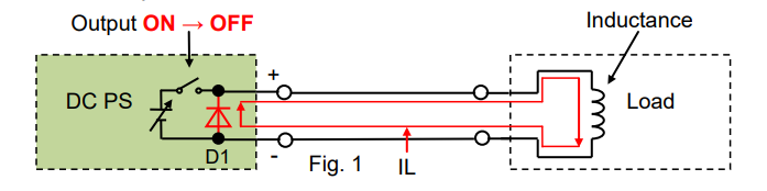
An inductive load such as a coil of wire is a passive element designed to store energy. When a current flows through it, electromagnetic energy gets stored. This stored energy is released creating reverse current right after its power source is disconnected. Without any protection, an inductive voltage spike, which is always opposite polarity, is seen across the inductive load when its supply current is suddenly interrupted.
See Figure 1 below. As an inductive kickback protection, usually a diode (‘D1’) or equivalent diode in a low-impedance state is placed in parallel with output terminals of a DC power supply. When the output is turned off, D1 can make a path for an inductive current (‘IL’) to suppress an inductive kickback, and thus D1 can protect the DC power supply.
Meanwhile no big noise occurs. This is because; 1) The output-off speed is slow at a microseconds-order interval. 2) IL through D1 never exceeds the current through the inductance in the load. 3) The current for this system can keep the small variations.
Particularly, D1 is so-called a flyback diode.
As shown in Figure 2, if another switch is placed to control the DC power supply’s output, there is no longer any path for IL so that a reversed voltage spike is induced when an output is turned off. As for the switching on/off speed, it is quite fast and the fastest one will be 1 µs or less. If a supply current is suddenly interrupted at this speed, an induced voltage across the inductance (‘L’) will become significantly higher as calculating: ‘V = L x dI/dt’.
As you can see below, a stray capacitance creates a loop for this high-frequency high voltage and a load wiring acts like an antenna to generate an EM noise. Once the noise enters into the DC power supply or any other devices in the system, it may deteriorate their performance or cause malfunction.
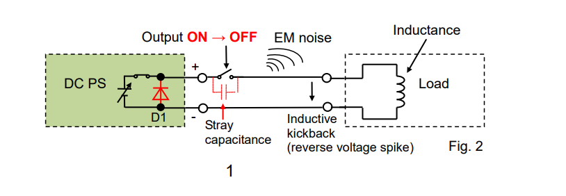
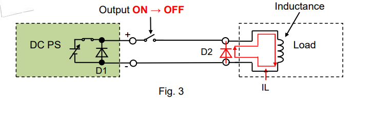
To reduce the noise, place a diode (‘D2’) close to the inductance as shown in Figure 3 to let IL flow through D2.
2. If you use capacitive load such as battery
2-1 Place diode in series
When charging a rechargeable battery, we should take care of a potential difference between a supply voltage and battery voltage. If the supply voltage is lower than the battery voltage, a power source such as a DC power supply acts like its output is turned off, and then the output voltage becomes equal to the battery voltage.
Usually, the DC power supply equips a bleeder circuit (‘R1’ in Figure 4) that let a battery discharging current (‘IBR’) flow through R1. Once IBR flows through RI, the battery will get discharged. Figure 5 shows that IBR is linearly proportional to the battery voltage.
If the output is kept to be turned off or the supply voltage is always lower than the battery voltage, the battery will be fully discharged.
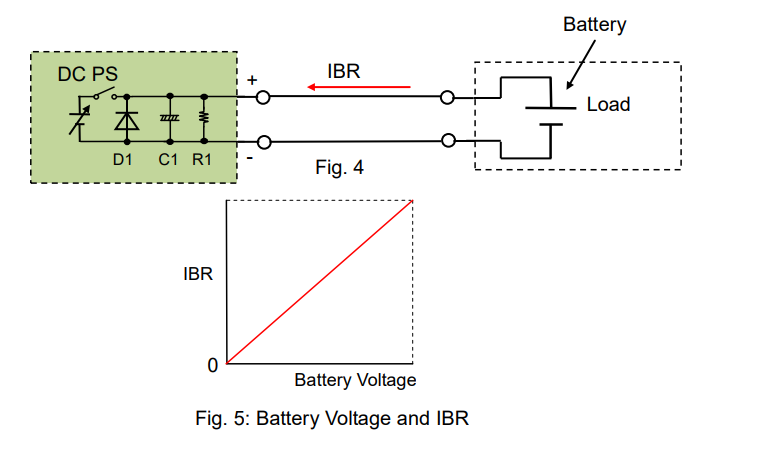
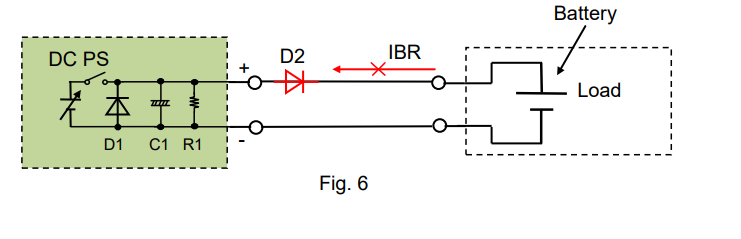
To block IBR, place a diode (‘D2’) in series as shown in Figure 6.
2-2 Remote sensing function
Battery charging is generally done with constant current constant voltage (CC-CV) method. In this mode, a battery is initially charged in CC mode until a battery voltage reaches a certain charging level, and then the charging process is switched to CV mode. This is to ensure that the voltage across the battery terminals does not exceed the maximum rated voltage of the battery while keeping the battery fully charged.
While in CC-CV mode, and a remote sensing function is turned on, you may want to put a remote sensing point at the battery terminals as shown in Figure 7. If so, the output voltage will fluctuate and worse still, the battery may be discharged through the sensing cable. This happens because a non-linear control is given by D2 or a voltage drop may occur with D2 at the battery terminals and it cannot be fully offset by the remote sensing function.

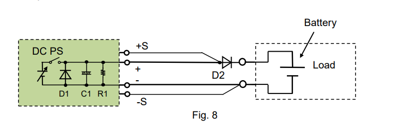
To avoid this, move the sensing point in front of D2 as shown in Figure 8. This can ensure that the DC power supply maintains the stable output. However, you should take care of the voltage drop caused by D2.
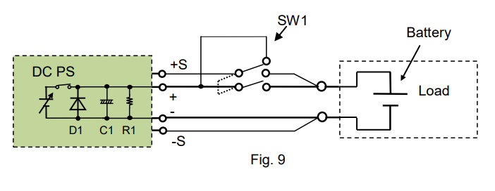
If you do not want D2 but want to use the sensing function, place a switch (SW1) on the sensing wiring (See Figure 9) to simultaneously turn on/off the both switches. In this case, when the DC power supply has the same voltage as the battery, turn SW1 on. To maximize the system efficiency, it is important to minimize the variations from the battery charging current and battery reverse (discharging) current.
3. If you use regenerative load
3-1 Sink current capability by DC power supply
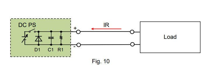
The bleeder circuit (R1) in a DC power supply can absorb a current, typically by several percent of its rated output current*.
If a reverse current (‘IR’) exceeds this level, an output voltage from the DC power supply unintendedly increases, and it may activate an overvoltage protection of the DC power supply. *Bipolar power supply can sink the same amount of the rated output current.
3-2 How to improve sink current capability
For example, let’s look at automotive components such as an electronic power steering (EPS) or a starter generator (SG). Both components use a brushless motor, and when it reverses the motor direction, the energy returns back to the power source. This is the regeneration process. In an actual car operation, the regenerative energy is going back to a car battery.
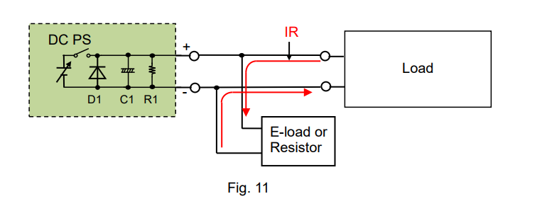
Let’s return to a DC power supply. While supplying power to such regenerative components, the DC power supply by itself cannot absorb their regenerative reverse current (IR).
See Figure 11 for the countermeasure; An electronic load or a resistor is placed on the load wiring to absorb IR. The electronic load is more efficient because it can easily control a maximum amount of IR.
For this system, it should be noted that the DC power supply should supply IR to the electronic load at least and the load current as needed. Please choose a DC power supply with a large enough current capacity to cover both currents.
Products Mentioned In This Article:
- DC Power Supplies please see HERE