Free Shipping logo FREE SHIPPING £75+
50 years of Telonic Instruments Ltd logo CELEBRATING 50+ YEARS
Price Match logo PRICE MATCH GUARANTEE

DC Electronic Load – Part 4: How Each Operation Mode Works with Other Modes?

Posted on: June 23rd, 2021 by Doug Lovell

We have so far explained the four major operation modes for electronic loads – 1) constant current 2) constant resistance 3) constant voltage and 4) constant power, in the previous white papers. Now this paper describes how these modes relate to each other and how each mode works on other modes.
4-1. Relationship between Operation Modes
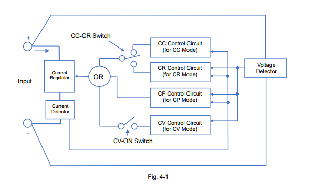
Figure 4-1 shows the block diagram for the control circuit structure of the electronic loads, where each operation mode is switched by.
The CC-CR switch closes either path of the constant current (CC) circuit or the constant resistance (CR) circuit. There is the OR circuit connected between the closed circuit (either CC or CR), the constant power (CP) circuit and constant voltage (CV) circuit. You will have the following three factors to determine which circuit is used, CP circuit or CV circuit: 1) the setting value for each control circuit 2) the input voltage of the electronic load and 3) the input current of the electronic load. In addition, the setting of the CV-ON switch determines whether to use the CV circuit or not.
Therefore, the electronic load users need to set at least the following settings:
1) Choose the CC mode or the CR mode to be used.
2) Choose whether to use the CV mode or not.
3) Set the appropriate settings for each operation mode.

As stated above, the four operation modes have the relationship with each other and the modes are switched depending on the setting values, the input voltage and the input current of the electronic load. In the next sections, we are going to explain the details how each mode is related and when exactly the modes are switched.
4-2. How CC Mode is Combined with Other Mode
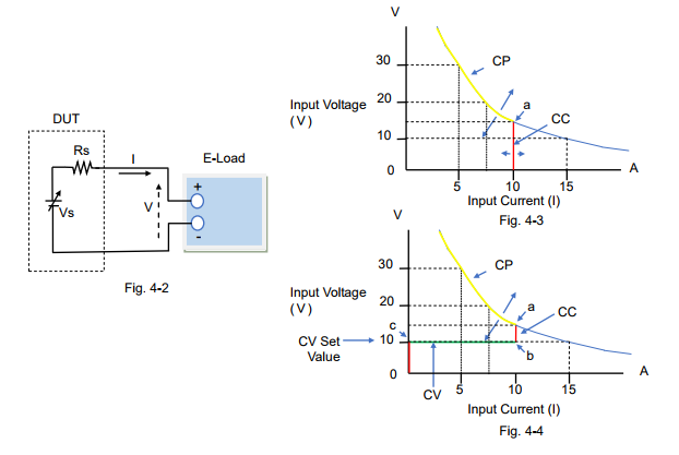
Figure 4-2 describes the circuit of the DUT and the electronic load; the components of the DUT are the voltage source (Vs) such as a power supply and the resistance (Rs) connected in series with Vs.
Figure 4-3 and 4-4 are the characteristic examples of how the input current flows with the Vs change when the CC mode setting of the electronic load is set to 10 A.
For figure 4-3, the CV mode is turned off. While Vs rises from almost 0 V to Point ‘a’, the electronic load operates in CC mode at 10 A as shown in the red line. After Vs exceeds Point ‘a’, the electronic load operates in CP mode*1 at 150 W as shown in the yellow line.
For figure 4-4, the CV mode is turned on (CV-ON). If Vs rises from almost 0 V, the input current does not actually exist until Point ‘c’ (= at the CV set value). After Vs exceeds Point ‘c’, the electronic load operates in CV mode until Point ‘b’, but it operates in CC mode after Point ‘b’ to Point ‘a’ at 10 A. After Vs exceeds Point ‘a’, the electronic load operates in CP mode*1 at 150 W as shown in the yellow line.
*1: Some electronic loads provide the overpower protection (OPP) function instead of the CP mode. The protection function will be described later in another white paper in this series.

Recommendations and Precautions for Use of CC Mode
To ensure the reliability of the CC mode operation, read the following advice:
1) If you want to use the CC mode only, you just set the CC mode setting. Turning off the CV mode is recommended, because if the CV mode is turned on (CV-ON), the input current does not actually exist until the input voltage reaches the CV set value. When setting the CP mode value or the OPP value, set it to the maximum.
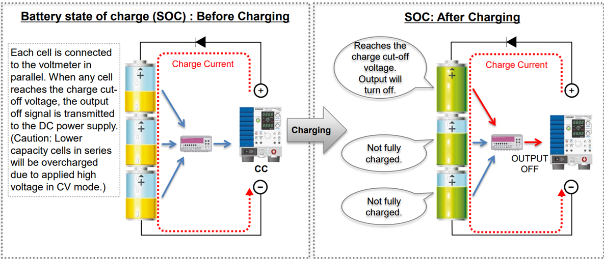
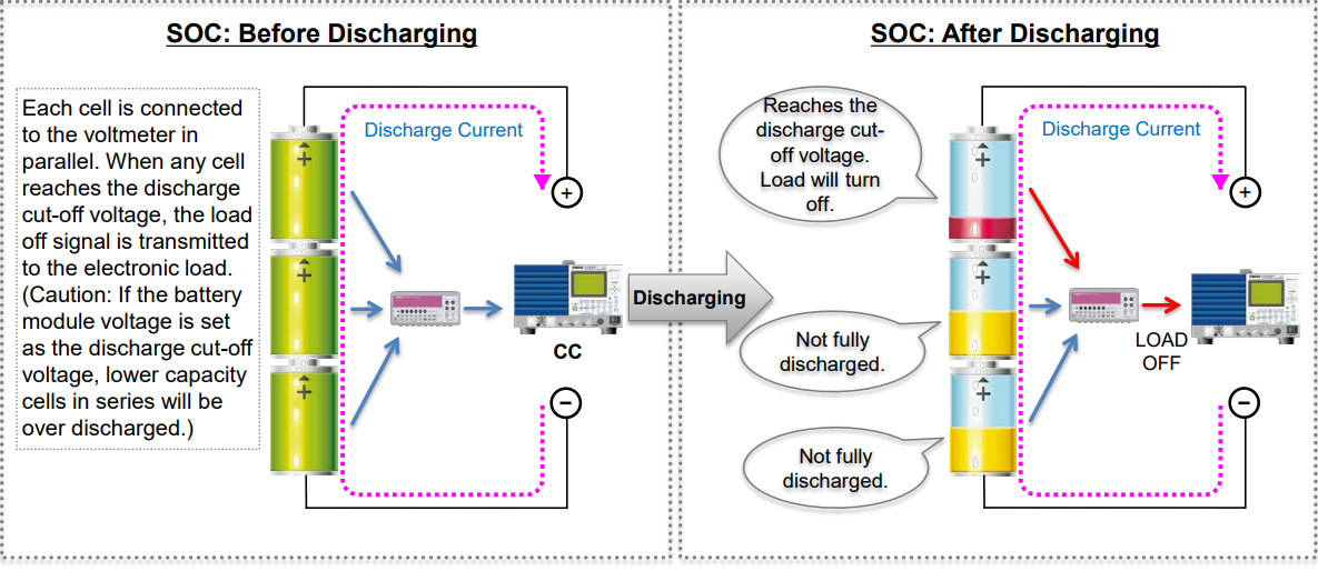
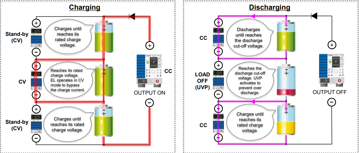
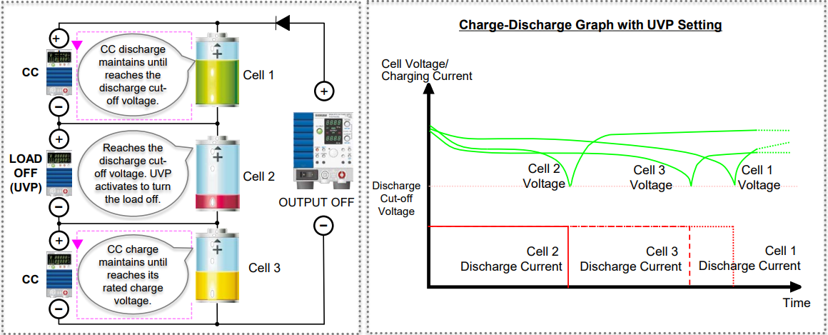
2) The CV mode (CV-ON) can be used as the over-discharge protection for rechargeable batteries. Initially the CC mode starts to discharge the battery until the battery voltage falls to the CV set value. Then, the mode switches from CC to CV and the electronic load stops the input current flow. This prevents the battery voltage from becoming too low to protect against over discharge.
3) When entering the CC mode, some electronic loads may automatically set the CP mode value to the maximum.
4-3. How CR Mode is Combined with Other Mode

For the system circuit, see figure 4-2 above.
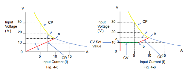
Figure 4-5 and 4-6 are the characteristic examples of how the input current flows with the Vs change when the CR mode setting of the electronic load was set to 1.5 Ω.
For figure 4-5, the CV mode is turned off. While Vs rises from almost 0 V to Point ‘a’, the electronic load operates in CR mode at 1.5 Ω as shown in the red line. After Vs exceeds Point ‘a’, the electronic load operates in CP mode*2 at 150 W as shown in the yellow line.
For figure 4-6, the CV mode is turned on (CV-ON). If Vs rises from almost 0 V, the input current does not actually exist until Point ‘c’ (= at the CV set value). After Vs exceeds Point ‘c’, the electronic load operates in CV mode until Point ‘b’, but it operates in CR mode after Point ‘b’ to Point ‘a’ at 1.5 Ω. After Vs exceeds Point ‘a’, the electronic load operates in CP mode*2 at 150 W as shown in the yellow line.
*2: Some electronic loads provide the overpower protection (OPP) function instead of the CP mode. The protection function will be described later in another white paper in this series.

Recommendations and Precautions for Use of CR Mode
To ensure the reliability of the CR mode operation, read the following advice:
1) If you want to use the CR mode only, you just set the CR mode setting. Turning off the CV mode is recommended, as stated above in ‘Recommendations and Precautions’ of Section 4-2. When setting the CP mode value or the OPP value, set it to the maximum.
2) The CV mode (CV-ON) can be used as the over-discharge protection for rechargeable batteries. For this CV mode operation, refer to ‘Recommendations and Precautions’ of Section 4-2. *Read as changing the CC mode to the CR mode.
3) When entering the CR mode, some electronic loads may automatically set the CP mode value to the maximum.

4-4. How CP Mode is Combined with Other Mode For the system circuit, see figure 4-2 above.
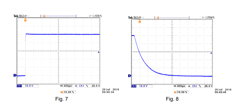
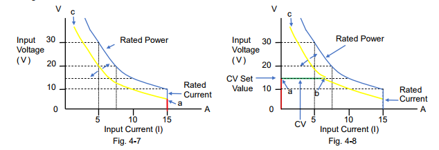
Figure 4-7 and 4-8 are the characteristic examples of how the input current flows with the Vs change when the CP mode setting of the electronic load was set to 100 W.
For figure 4-7; the CV mode is turned off, and the CC mode or the CR mode is set to Automatic or the maximum rating value. If Vs rises from almost 0 V to Point ‘a’, the electronic load operates in CC mode at 15 A (rating current) as shown in the red line. After Vs exceeds Point ‘a’, the electronic load operates in CP mode at 100 W as shown in the yellow line and it may reach Point ‘c’ with Vs change.
For figure 4-8, the CV mode is turned on (CV-ON). While Vs rises from almost 0 V, the input current does not actually exist until Point ‘a’ (= at the CV set value). After Vs exceeds Point ‘a’, the electronic load operates in CV mode until Point ‘b’. After Vs exceeds Point ‘b’, the electronic load operates in CP mode at 100 W as shown in the yellow line and it may reach Point ‘c’ with Vs change.

Recommendations and Precautions for Use of CP Mode
To ensure the reliability of the CP mode operation, read the following advice:
1) When setting the CP mode value and the CR mode value, set them to the maximum.
2) If you want to use the CP mode only, you just set the CP mode setting. Turning off the CV mode is recommended, as stated above in ‘Recommendations and Precautions’ of Section 4-2.
3) The CV mode (CV-ON) can be used as the over-discharge protection for rechargeable batteries. For this CV mode operation, refer to ‘Recommendations and Precautions’ of Section 4-2. *Read as changing the CC mode to the CP mode.
4) In CP mode, if you do not want a high input current, you can regulate it by setting a lower CC mode value or setting an overcurrent protection (OCP).
4-5. How CV Mode is Combined with Other Mode For the system circuit, see figure 4-2 above.
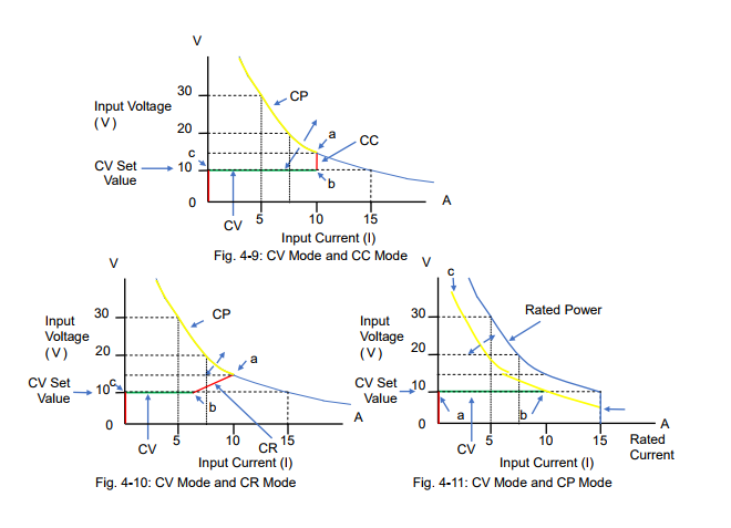
Figure 4-9, 4-10 and 4-11 are the characteristic examples of how the input current flows with the Vs change when the CV mode setting of the electronic load was set to 10 V.
Figure 4-9 shows the combination between the CV mode and the CC mode. For the CV mode operation, read Section 4-2 describing figure 4-4 ‘the CV mode is turned on (CV-ON)’. The input current does not actually exist until Vs reaches the CV set value. After Vs exceeds Point ‘c’, the electronic load operates in CV mode until Point ‘b’ as shown in the green line. Then, after Vs exceeds Point ‘b’, the mode switches to the CC mode until Point ‘a’. If Vs rises above Point ‘a’, the mode switches to the CP mode*4.
Figure 4-10 shows the combination between the CV mode and the CR mode. For the CV mode operation, read Section 4-3 describing figure 4-6 ‘the CV mode is turned on (CV-ON)’. Figure 4-10 looks similar to figure 4-9, except that the mode is in the CR mode from Point ‘b’ to Point ‘a’. Figure 4-11 shows the combination between the CV mode and the CP mode. For the CV mode operation, read Section 4-4 describing figure 4-8 ‘the CV mode is turned on (CV-ON)’. While Vs is lower than Point ‘a’ (= at the CV set value), the input current does not actually exist. When Vs exceeds Point ‘a’, the electronic load operates in CV mode until Point ‘b’ as shown in the green
line. After Vs exceeds Point ‘b’, the electronic load operates in CP mode.
*3: ‘CV-ON’ can be referred to as ‘+CV’.
*4: Some electronic loads provide the overpower protection (OPP) function instead of the CP
mode. The protection function will be described later in another white paper in this series.

Products Mentioned In This Article:

Kikusui Electronic Loads please see HERE

How to Double Output Voltage from Two PBZ through BTL* Connection

Posted on: June 23rd, 2021 by Doug Lovell

Here is an introduction on a method to achieve a double output voltage using two units of PBZ. The actual connection of PBZs is shown in Figure 1 as;
-‘OUT’ terminals are used for output.
– Only ‘COM’ terminal can be earthed for output, if required.
For the frequency characteristics, it is limited to 50 kHz in CV (100 kHz in normal) and limited to 8 kHz in CC (10 kHz in normal) as specification. This method enables you to use PBZ as high-speed bipolar power supply for your usage and needs.
*BTL (Bridged Transformer Less)
1. Connection Overview:
PBZ BTL Master (BTL Master) outputs the positive voltage (+V), while PBZ BTL Slave (BTL Slave) outputs the negative voltage (-V) through ‘OUT’ terminal. So, the amount of output voltage on the RL will double (2V).
How to Connect PBZ:
1) Connect ‘COM’ terminals to each other.
2) Connect each ‘OUT’ terminal to RL.
3) Make sure that rear ‘OUT’ terminal is not connected to ‘GND’ terminal. You can connect rear ‘COM’ terminal to ‘GND’ terminal, if needed.
4) Connect ‘CV MONITOR (pin 13, 18)’ of J1 Connector on BTL Master (rear side) to ‘EXT SIG IN’ on BTL Slave (front side).
5) Connect ‘TRIG OUT’ on BTL Master (rear side) to ‘TRIG IN’ on BTL Slave (rear side) to build trigger synchronization.

2. Settings
After connecting as shown in Figure 1, please make the settings below.
Note) It is recommended that you return BTL Master/Slave to the factory default prior to the settings;
– Switch POWER on while holding down SHIFT key to return to the factory default.

2-1 Settings for BTL Master
To synchronize the OUTPUT ON/OFF operation between BTL Master and Slave, set CONFIG [3] (3/7) > SYNCHRONOUS > OPERATION as below (Refer to page 89 of user’s manual):
(1) Press CONFIG key several times to move to the menu 3/7.
(2) Specify SYNCHRONOUS > OPERATION > MASTER using the knob.
(3) The setting is confirmed once ‘MASTER’ is displayed.
2-2 Settings for BTL Slave
1) To synchronize the OUTPUT ON/OFF operation between BTL Master and Slave, set CONFIG [3] (3/7) > SYNCHRONOUS > OPERATION as below (Refer to page 89 of user’s manual):
(1) Press CONFIG key several times to move to the menu 3/7.
(2) Specify SYNCHRONOUS > OPERATION > SLAVE using the knob.
(3) The setting is confirmed once ‘SLAVE’ is displayed.
2) BTL Slave is synchronized with BTL Master and uses ‘CV MONITOR’ as an external signal source via ‘EXT SIG IN’ instead of using its internal signal.
Set CONFIG [2] (2/7) > SIGNAL SOURCE > SELECT as below (Refer to page 88 of user’s manual):
(1) Press CONFIG several times to move to the menu 2/7.
(2) Specify SIGNAL SOURCE > SELECT > EXT using the knob.
(3) Specify SIGNAL SOURCE > EXT SELECT > BNC using the knob.
(4) The setting is confirmed once (2) and (3) is specified.
3) Set the external signal circuit gain and output polarity to produce the negative output (-V). Specify CONFIG [2] (2/7) > SIGNAL SOURCE > EXT GAIN as below (Refer to page 88 of user’s manual):
(1) Press CONFIG several times to move to the menu 2/7.
(2) Specify SIGNAL SOURCE > EXT GAIN as:
PBZ20: -10.0
PBZ40: -20.0
PBZ60: -30.0
PBZ80: -40.0
The polarity will be inverted by specifying the negative output value.
(3) The setting is confirmed once (2) and (3) is specified.
(4) Perform the gain adjustment to exactly match the output between BTL Master and BTL Slave in step 2.

3. How to Operate
・ Turn OUTPUT on/off by BTL Master only.
・ Specify the CV/CC value and current limit value by BTL Master only. ・ If used the same rated voltage models, the output voltage will double. ・ Set RESPONSE of BTL Slave to the fastest.
・ Apply the connection control to BTL Master, if needed.
4. Output Results
4-1 CV Output – Rising/Falling Characteristics

PBZ40-10 x 2

4-2 CC Output – Rising/Falling Characteristics

PBZ40-10 x 2

5. Precaution in Use and Others
5-1 Connecting with Different Rated Models
It is available to connect PBZs with the same rated voltage and different rated voltage. When connecting PBZs with different rated voltage, the output voltage of BTL Slave is specified by the same ratio of those of BTL Master. In fact, the total output voltage will not double.
E.g.) BTL Master: PBZ40, BTL Slave: PBZ20; If the output voltage from PBZ40 is set to 20V, the output voltage from PBZ20 will be 10V and the total applied voltage on the load will be 30V.
5-2 Precaution in Measurement
Please use a differential probe when measuring the output voltage with an oscilloscope. Without a differential probe, the output will be shorted at the oscilloscope probe, and it may be burnt out.
5-3 How to Achieve CV 100KHz
As shown in Figure 6, please use PBZs as BTL amplifier.
Connect a function generator (FG) through ‘EXT SIG IN’ terminals. FG is used as an external signal source to reach your desired output voltage. By using FG, GAIN is set to be negative to invert BTL Slave polarity. To synchronize the OUTPUT ON/OFF operation between BTL Master and Slave, please build trigger synchronization.
With this method, only ‘COM’ terminals can be grounded.

Products Mentioned In This Article:

  • PBZ Series please see HERE

Useful Functions and Precautions for Using L-Load/C-Load in PCR-LE Series

Posted on: June 23rd, 2021 by Doug Lovell

1. When Using Inductive Load (L-Load)1-1 Soft Start

A typical L-load is a motor load. E.g.) If using an induction motor load, the startup current can be 5 times (or more) larger than the normal startup current and it flows for several hundred ms.
In this situation; 1) The motor load becomes inductive. 2) The power factor is approx. 0.5 at peak current.
PCR-LE Series features the Soft Start function to gradually increase the startup voltage when OUTPUT is turned on. If Soft Start is set to ON in the above situation; 1) The startup current (peak current) decreases. 2) The power factor is approx. 0.65 at peak current. 3) The startup voltage gradually rises for up to 3 seconds.

1-2 Output Capacity Reduction Due To Power Factor

As described in the above, the power factor decreases and the higher current flows for several hundred ms with the motor load. Since this period is quite short, it can be considered as the instantaneous peak current. The instantaneous peak current ratio decreases due to the power factor (see the table below).

2. When Using Capacitive Load (C-Load)
2-1 Soft Start
PCR-LE Series supports the DC output mode. In DC mode, the peak current in C-load changes with the voltage rise slope and can be calculated as: I=LdV/dt. Since the voltage rise time of PCR-LE Series is from 15μs to 70μs, the high peak current may flow depending on the capacitor size. To prevent it, turn Soft Start on to decrease the peak current.
2-2 Surge Suppression Function
Generally, if the output is suddenly interrupted, the L-load releases energy. It means that;
1) It becomes the high impedance state due to the sudden interruption. 2) The L-load generates the surge voltage and it is biased to the power supply as overvoltage.
To prevent it, PCR-LE Series features the Surge Suppression function. When OUTPUT is turned off while Surge Suppression is set to ON (factory default setting), the output voltage stays at 0V for approx. 200μs and then the output impedance becomes high.
For C-load or capacitive DUT:
Surge Suppression is ON: If OUTPUT is turned off in DC mode, the output voltage rapidly falls (see Fig. 3) and the current flows from DUT to PCR-LE Series.
Surge Suppression is OFF: See Fig.4. This is equivalent to having the interruption due to wiring disconnection. It may meet the requirements of IEC6100-4-29 (interruption in high impedance state).

2-3 Response Speed

PCR-LE Series uses a high-speed linear amplifier to provide high-quality/high-stability output. It can freely control the broadband waveform; however the output may become unstable depending on the capacitive load capacity or wiring conditions. To improve it, you can set the response speed of the internal amplifier to SLOW.
Response speed mode for PCR-LE Series:
Rated power capacity is 4kVA or less: FAST, MEDIUM, SLOW Rated power capacity is 6kVA or more: MEDIUM, SLOW

Products Mentioned In This Article:

PCR-LE Series please see HERE

Which Power Supply is Most Suitable to Run DC Motor?

Posted on: June 23rd, 2021 by Doug Lovell

When choosing a power supply to run a DC motor, the first and most important thing you need to consider is a maximum current that your motor will use. DC motor typically requires a startup current which is quite a lot higher than its running current. Due to this, not all DC power supplies can provide sufficient power to DC motors.
In this white paper, we will take a look at the capability of our bipolar DC power supply PBZ20-20A, which can supply a short-term peak current up to six times its rating current (± 120 Apk CV).
Below, we are going to share our measurement results that show how PBZ20-20A worked with a DC motor.
1. Purpose of Measurement
The purpose of this measurement is to determine the performance of PBZ20-20A on a brushed DC motor by measuring the voltage and current waveforms.
2. Wiring Connection

▪ Each was crimped: the positive ends and negative ends of output and remote sensing wires. ▪ Wiring length: Approx. 1 m for both remote sensing and output wiring
▪ Wiring cross section: Output wiring: AWG16 1.31 mm² (1.25 sq),
Remote sensing wiring:AWG24 0.205 mm² (0.2 sq)
▪ The twisted pair was made on the output and remote sensing wire. 3. Measurement Conditions
▪ Output mode: CV mode
▪ Response setting: CV mode voltage response: 3.5 μs/100 μs, CC mode current response: 35 μs/1 ms * PBZ20-20A can output a peak current only when the current response is set to 1 microsecond in CV
mode.
▪ Limit setting: Voltage limit: + 14 V (protect the motor from overvoltage),
Current limit: ± 22 A (output current setting: max.)
▪ Voltage setting: 12 Vdc
▪ Motor to be used: Brushed DC motor – details unknown.

4. Results
1) Response setting: CV 3.5 μs, CC 35 μs

▪ The motor voltage was oscillated because the output current was limited (no peak current was provided).
2) Response setting: CV 100 μs, CC 1ms

▪ CV mode voltage response setting was changed: 3.5 μs to 100 μs. ▪ CC mode current response setting was changed: 35 μs to 1 ms.
▪ Since the current response was set to 1 microsecond, PBZ20-20A could output the peak current. ▪ The voltage oscillation was reduced.
3) Response setting: CV 100 μs, CC 1ms with remote sensing turned on

▪ With the remote sensing turned on, the voltage became more stable.

4) When the output was turned off:

▪ When the output was turned off, the followings happened;
1) The reverse motor current was generated and then interrupted. It took approx. 10 microseconds.
2) The motor voltage started to rise.
3) The overvoltage protection (OVP ALM) was activated.
The reason why this happened was because the PBZ20-20A’s relay contact was suddenly opened (disconnected).

5) Extended view of No. 4

▪ The motor voltage reached approx. 28 Vdc max.
6) When the motor voltage was changed from 12 Vdc to 0 Vdc by the sequence control:

▪ The voltage rising was not found under the sequence control.
7) After the output was turned off:

▪ Until the motor was fully stopped, the motor reverse voltage had been applied to PBZ20-20A.
▪ The voltage detection circuit in PBZ20-20A kept closed (connected) even when the output was turned off. This could be a small path to allow a little bit of motor reverse current (discharging current) to flow back to PBZ20-20A.
5. Measurement Summary
▪ When the PBZ20-20A’s output was turned off, the brushed DC motor started functioning like a generator inverting the direction of its current and forcing it into PBZ20-20A.
▪ As an explanation of measurement No. 4; when the output was turned off, the reverse current flew for approx. 10 microseconds. However, the output relay contact in PBZ20-20A was open, so there was no path for the current to flow. This sudden release of energy induced the transient voltage spike.
▪ PBZ20-20A provided the peak current at 45 A for the brushed DC motor. The duration that the output current exceeded 20 A was approx. 8 microseconds.
6. Recommendation
▪ Bipolar power supply can sink a reverse current, while DC power supply cannot. If using a DC power supply and motor, connect an electronic load in parallel to absorb a reverse current.
▪ To protect PBZ20-20A from an overvoltage, wait until an output current reaches 0 A before turning an output off.
7. Conclusion
The above measurement results prove that PBZ20-20A can meet the requirement to run the DC motor to be tested. To identify whether PBZ20-20A can sufficiently power your DC motor or not, we recommend that you carefully read the data sheets or check the specifications.

Products Mentioned In This Article:

  • PBZ Series please see HERE

How to Balance Battery Module Charge-Discharge

Posted on: June 23rd, 2021 by Doug Lovell

With the recent diversification of battery module application such as for automotive and backup, more and more users want to conduct a battery module charge-discharge test, besides of an individual cell battery test.
As a battery management system has been greatly developed to maximize battery’s capacity, the practical needs to perform evaluations on balancing battery charge-discharge are increased. Here you will find the method to balance the battery charge-discharge by using our DC power supply and electronic load.

Unbalancing Battery Module Charge

CC flows into each cell with different capacity and SOC unbalance. Cells with less charge capacity always reach the charge cut-off voltage faster. → The battery module cannot reach its full capacity.

Unbalancing Battery Module Discharge

CC is sunk from each cell with different capacity and SOC unbalance. Cells with less discharge capacity always reach the discharge cut-off voltage faster. → The battery module cannot be fully discharged.

Balancing Battery Module Charge-Discharge

Electronic loads are separately connected to each cell in parallel to perform the balancing charge-discharge.

Balancing Battery Module Charge
Electric loads connected to each cell in parallel operate in CV mode.
Balancing and optimal charge to series cells is available by performing the CC-CV charge; The CC setting is set to a DC power supply and the CV setting is set to electronic loads.
Note: 1) The CC limit for electronic loads should be set higher than the charge current. 2) The electronic load alarm should be linked to the power supply output.

Balancing Battery Module Discharge
Electric loads connected to each cell in parallel operate in CC mode independently.
To stop the discharge; 1) Set the discharge cut-off voltage as under voltage protection (UVP) to turn the load off. 2) Set the discharge cut-off voltage as the CV set value to perform the CC+CV operation. Note: 1) The negative input terminal in each electronic load should be isolated. 2) With the external analogue control, the control signal terminal should be isolated.

Products Mentioned In This Article:

  • DC Power Supplies & Electronic Loads please click HERE

DC Power Supply Sinks Current when Output is Turned Off

Posted on: June 23rd, 2021 by Doug Lovell

When using a DC power supply for charging a load such as battery or capacitor, it is important to note that the DC power supply absorbs a current from such loads when the output is turned off. Here we are going to further explain this power supply’s behaviour; DC power supply, in general, comprises a bleeder circuit to discharge a power supply’s electrolytic capacitor at its output terminal. If the output is turned off after charging a battery or capacitor, the bleeder circuit sinks the current from them. The purpose of the bleeder circuit is to quickly discharge the voltage stored in the power supply’s electrolytic capacitor for safety reasons.
Now look at the following figures. Figure 1 shows the equivalent circuit of the DC power supply output and Figure 2 shows the example of the sink current measurement. This example data may help you estimate a discharge current and voltage change of your load.
1. Equivalent Circuit of DC Power Supply: When output is turned off
As shown in Figure 1, the sink current (shown in red arrows) flows through the 39-kΩ resistance and voltage-following constant current circuit (CC varies by voltage).
Sink current

2. Sink Current: When output is turned off
Figure 2 is the example of the sink current measurement through above resistance and circuit

When the DC power supply is turned off, the sink current flows through the 39-kΩ resistance only.

Products Mentioned In This Article:

  • DC Power Supplies please see HERE

How to use the voltage correction function on frequency response

Posted on: June 23rd, 2021 by Doug Lovell

The PCR-WE can output up to 5 kHz, but it has frequency response as shown in the figure below. The response is about -3dB at 5kHz. For example, the waveform in the figure below is for 120 Vrms, 5 kHz.

Voltage amplitude correction
The PCR-WE has a function to correct the attenuation due to the frequency response of the output. Please refer to the “The soft sensing function is used” page of the User’s Manual.
Steps to enable features:
1. Turn off the Output.
2. Set the Output Voltage.
3. Press Oher button (Shift + Memory) > 1/2 (F6) > COMPEN (F2) > SENS.-S (F3).
4. Press ENT.
“SENS.-S” is displayed on the panel.
5. Press 1/2 (F6) > SOFT.SENS (F2) > S.POINT (F5) > O.TERM (F2)

Set the sensing point in output terminal. 6. Press ESC > V.CTRL (F2) > AC (F2)

Corrected waveform
The output voltage is 120 Vrms.

Products Mentioned In This Article:

  • PCR-WE Series please see HERE

DC Electronic Load – Part 1: What is a DC Electronic Load?

Posted on: June 23rd, 2021 by Doug Lovell

Beginners who have never used an electronic load may well get confused with the difference between electronic loads and power supplies. They sometimes wonder ‘why the electronic load does not provide any output…?’
While similar in appearance, electronic loads are totally different from power supplies. It is not often you get to see them but it is suitable for specific applications such as working as variable resistors, in a part of high-power systems, to test power supplies.
From here we offer a great series of white papers that give you a thorough understanding of the basics and use of electronic loads, ranged from what it is through to how it is used including its operating principle. Part 1 explores the fundamentals of electronic loads.
* This series focuses on explaining DC electronic loads only; AC electronic loads will not be included.
1. Fundamentals of DC Electronic Load
DC electronic loads are used in a range of DC power supply tests. We will discuss why they are ideally suited for power source testing, in contrast with a popular device, DC power supply.
1-1. Electronic Load and Load of Horse-Drawn Vehicle
Electronic loads can help you investigate the ability of power supplies. This can be compared to the method of determining an ability of a cart horse. Figure 1-1 shows that the horse is pulling the cart of mass 490 kg (approx.1080 lb). If the horse cannot pull a cart of mass 500 kg (approx. 1102 lb), it proves that this horse has the ability of pulling the cart up to 490 kg (approx.1080 lb).

You now understand how electronic loads are different from power supplies; power supplies apply a voltage to DUTs, while electronic loads sink a current from DUTs. So you can now really understand the answer to ‘why electronic loads do not provide any output…?’
1-2. Act as Substitute for High-Power Components
Electronic loads are used to test power source devices. According to Ohm’s law, if the resistor is connected to the output of the power source device (DUT), the current flows from the DUT (See Figure 1-3). Electronic loads can be used as substitute for the resistor. Furthermore, users can easily adjust the resistance value on their own from electronic loads.

In other words, electronic loads can act as a variable resistor, and also achieve tens of kilowatts of power. Instead of using different sizes of fixed resistors, one unit of electronic load allows you test the load dynamically in a repeatable fashion.
Electronic load circuits regulate the resistance value. Based on the performance of circuit functions, electronic loads behave like a 1) Variable resistor 2) Variable Zener diode 3) Load simulator, which described in more detail in the following sections.
1) Act as Variable Resistor
Figure 1-4 shows that the variable resistor is connected to the DUT.
Figure 1-5 shows the relationship between the voltage (V) across the resistor and resistor’s current (I). This relationship in a circuit of the resistor produces a straight line. In the graph, the resistance (R) is the slope. The slope varies according to the resistance value.
During the DC power supply tests, the electronic load controls the resistor’s current by adjusting the resistance value.

The most important aspect is that “the variable resistor can regulate the current flow in the circuit.” If the electronic load acts as a variable resistor, it means that you can control the current based on your test applications or conditions with electronic loads. Furthermore, electronic loads have a capability to provide a constant power or constant current mode, which are described in the next article.
2) Act as Variable Zener Diode
Figure 1-6 shows that the Zener diode is connected to the DUT.
Figure 1-7 shows the relationship between the voltage across the Zener diode and its current. Once the voltage reaches a certain point known as the Zener voltage (Vz), the Zener resistance dramatically decreases. The Zener diode clips any voltage that exceeds the Zener voltage (Vz). In an electronic load, you can set a voltage (equivalent to the Zener voltage) that remains constant regardless of changes to its input current (I). This set voltage is called the constant voltage (CV) and this operation is called the CV mode.

If the DUT is motor in figure 1-6, the DUT may provide a regenerative power by reversing the direction of the motor rotation and it may cause a reverse voltage spike. To prevent it, set the CV voltage so that the voltage will not exceed this CV set voltage.
3) Act as Load Simulator
High-performance electronic loads can simulate various power states so they can be used in diverse applications instead of using a real load. You just select an appropriate electronic load that can exactly simulate your actual load with the waveforms in the example below;
Figure 1-8 shows that the test waveform current flows on a circuit.
Figure 1-9 shows the current waveform simulation example for lamp current.
Figure 1-10 shows the pulsed current waveform simulation example.

Products Mentioned In This Article:

Kikusui Electronic Loads please see HERE


Two Methods to Absorb Motor’s Regenerative Current Using Electronic Load

Posted on: June 23rd, 2021 by Doug Lovell

There are two methods to absorb motor’s regenerative current; Voltage Clipping Method and Bleeder Method. The following describes the characteristics, functions and precaution for the methods. Fig.1 illustrates the typical test system.

1. Voltage Clipping Method
This method is to set the electronic load in CV mode to clip the motor’s regenerative current. If the regenerative current is not fully followed, overshoot may occur even with this method. The overshoot occurs depending on the relationship between the rise time of regenerative current and CV switching time of electronic load:
-The faster the CV switching time is, the more voltage can be saved.
-Motor impedance determines the rise time of regenerative current. The larger the impedance is, the slower the rise time of regenerative current becomes.
This allows CV switching to perform properly, and the overshoot can be suppressed.

1-1 Response Time for CV Mode with Typical Electronic Load
The following are the response time for CV mode with PLZ205W. In PLZ-5W Series, you can choose two modes for CV switching. Fig.2 is for Fast mode, Fig.3 is for Normal mode. Measurement Condition:
– 15V is set to PLZ205W for the CV setting.
– When approx. 12V is applied to PLZ205W, PBZ60-6.7 applies rapid constant current (approx.30μs).
The yellow line shows when the voltage was clipped: Fast Mode: approx. 300μs Normal Mode: approx. 3ms

In Fig.2 and Fig.3, the overshoot voltage was much high. It is because PBZ60-6.7 applied 60V and the rise time of current is fast (approx. 30μs). Fig.4 illustrates the test circuit.
1-2 Precaution in use
Since impedance varies by motor, pre-test is recommended to check whether: – Overshoot is clipped until it meets your satisfaction.
– Oscillation occurs depending on the combination and compatibility between the motor inductance or load cable inductance and electric load.
2. Bleeder Method
This method is to set the electronic load in CC mode to always flow the higher current than regenerative current into the electronic load. When the regenerative current flows, the voltage of electronic load becomes higher than the power supply voltage. In such condition, the power supply current is cut off and the regenerative current flows into the electronic load to clip the regenerative voltage.
To drive the motor:
– Power supply should have the output current capacity for ‘motor drive’ + ‘regenerative current’. – At least the same amount of regenerative current should be always flowed into electronic load. Fig. 5 shows the result to clip the regenerative current with this method. This test circuit is shown in Fig.1.

The merit of this method is that you can clip the voltage without overshoot. On the other hand, the current of electronic load for the regenerative current is continually being wasted. Therefore, please be noted that the system consumes quite a large power.

Products Mentioned In This Article:

  • Kikusui Electronic Loads please see HERE

Choosing Electronic Load that Best Fits Your Switch Testing System

Posted on: June 23rd, 2021 by Doug Lovell

The switch on/off testing can be performed with a combination of DC power supply and electronic load (See Figure 1). To successfully conduct the testing, it is important to know that the current flow through the switch varies by the electronic load specifications or settings. Especially during the life testing, you should be aware that it may affect the lifetime of test switch.
This white paper shares the measurement results using our different electronic loads and helps you understand how to choose or set an electronic load for your switch testing system.

1. Switch Testing System Configuration and Test Conditions
Figure 1 shows the system configuration diagram for the switch on/off testing.
Test Conditions: Set DC voltage to 14.6 V by DC power supply. Set PLZ150U or PLZ70UA in CC or CR mode.

3. Important Points for Switch Testing System
Consider the following points when preparing the testing system;
1) Almost no current is supplied during the chattering at switch-on (See Fig. 2, 4, 6 and 8). *1
2) Set Soft Start to 0.1 ms to start the current flowing as soon as possible.
3) The magnitude of current differs in CC mode and CR mode at switch-off. Higher current can flow in CC mode (See Fig. 3, 5, 7 and 9).
4) Connecting an electrolytic capacitor in parallel with the electronic load input is also effective to simulate the start-up inrush current (switch-on surge). With the capacitor, very little voltage will be applied on the both side of the switch at switch-off.
5) Set the CV value (+CV mode) if using 0 V input operating voltage type of PLZ Series, such as PLZ70UA, PLZ164WA or PLZ664WA.
*If the power supply’s output is turned off first, the electronic load may cause an alarm. Turn off the electronic load first and then turn the power supply’s output off.
6) Overcurrent testing can be also performed in the same system; Use an electronic load whose capacity is large enough.
Under the above test conditions, PLZ150U can provide the better results than PLZ70UA.
*1: The Soft Start function is gradual starting up of an electronic load to avoid the overshoots of current. While the short-pulse voltage is first applied to an electronic load during the chattering, the Soft Start will minimize large startup currents from flowing. It delays the current start-up time for approx. 0.1 – 0.2 s.

Products Mentioned In This Article:

  • Kikusui Electronic Loads please see HERE

How to use the power line disturbance simulation function of PCR-WE

Posted on: June 23rd, 2021 by Doug Lovell

Voltage dips, short interruptions and voltage variations immunity tests of the IEC 61000-4-11 standard can be easily tested using the power line disturbance simulation function of PCR-WE.
As an example, it explains how to set the voltage dip test. You can easily execute tests under the test conditions specified in the standard in a few steps.

IEC61000-4-11 Voltage dip

a Classes as per IEC61000-2-4; see Annex B.
b To be defined by product committee. For equipment connected directly or indirectly to the public network, the levels must be less severe than Class 2.
c “25/30 cycles” means “25 cycles for 50Hz test” and “30 cycles for 60Hz test”

Simulation setup procedure

First, determine the exam level and duration.
Let’s create a simulation waveform of 0.5 cycle with 0% voltage amplitude of Class 2. (As an example, the test voltage and frequency are 120V 60Hz.)
The duration is 0.5 cycle, so it is 8.3ms (= 0.5/60Hz). The test level is 0%, so it is 0V.

Next, set the simulation function.

1. Set the steady-state voltage and frequency. (ex. 120V 60Hz)
2. Press SIM>COND(F4) to set the conditions.
3. POL ”+” / T1 TYPE “TIME” / T5 TYPE “TIME”
4. Press ESC to return to the previous screen.
5. Press EDIT(F5) to set the parameters.
6. T1 ”0” / T2 “0” / T3 “10ms“ / T4 “0” / T5 “10s” / T3 VOLT “0”
7. Press ESC to return to the previous screen.
8. Select LOOP(F3) to set the number of repetitions. (ex. 3 times) Configuration is complete.

Press SIM > RUN (F1) to execute a power line disturbance simulation.
Using a trigger out signal makes it easier to observe the waveform with an oscilloscope.

Products Mentioned In This Article:

  • PCR-WE Series please see HERE

How Does Surge Suppression Work in PCR-LE/LE2 Series?

Posted on: June 23rd, 2021 by Doug Lovell

PCR-LE/LE2 Series feature the Surge Suppression function that involves the process of protecting PCR-LE/LE2 from voltage spike.
You can choose Surge Suppression to turn on or off depending on your load condition. If you want to avoid any voltage overshooting or undershooting, always set Surge Suppression to on. However, when you use a load with regenerative feedback (e.g. capacitive load or battery), it is recommended that Surge Suppression is set to off. In this white paper, we are going to provide the details of Surge Suppression function and make clear the difference between when Surge Suppression is set to on and off.
1. Surge Suppression: On
Surge Suppression is set to on as factory default.

1-1. Timing Chart
Figure 1 shows the timing chart when Surge Suppression is on;
1. The output is in the high impedance state while the output is turned off.
2. When the output is turned on, the voltage stays at 0 V for first 200 microseconds, and then the voltage rises to the set value.
3. When turning off the output, the voltage firstly falls to 0 V for approx. 200 microseconds, and then the output stays in the high impedance state.
Thanks to this ‘staying at 0 V for approx. 200 microseconds’ behaviour, Surge Suppression can prevent the voltage overshooting or undershooting when the output is turned off. Even if an inductive kickback (reverse voltage surge) occurs due to an inductive load, PCR-LE/LE2 can absorb a reverse current during these 200 microseconds.

The reverse current means a discharging current for the inductive load. If the discharging current may affect your load state, set Surge Suppression to off.

For your reference, Table 1 shows the high impedance value.

1-2. Voltage Waveforms
The following figures are the actual voltage waveforms when the output was turned off with different loads. Conditions: Output 50 Vdc by PCR500LE and turn it off.
No-load state: See Figure 2. The voltage kept at 0 V for approx. 200 microseconds. The undershooting was seen soon after the output shifted to the high-impedance state.
With the lower load resistance (See Figure 3 and 4) or large capacitor (See Figure 5), the undershooting was reduced or almost eliminated.

The undershooting was caused by 1) a switching circuit in PCR500LE that switches from low to high impedance 2) capacitors (X-capacitor and Y-capacitor) at PCR500LE’s output terminal and 3) internal wirings in PCR500LE.
Quite small energy was stored into the internal wirings in PCR500LE when the output was turned off. This residual energy was dissipated in the load resistance or capacitance. Thus, the voltage undershooting was suppressed, as shown in Figures 3 through 5.
2. Surge Suppression: Off
You can set Surge Suppression to off;
If you do not want to let the reverse current flow back to PCR-LE/LE2 when the output is turned off, or
If you simulate the event like; While PCR-LE/LE2 provides a DC output to an inductive load, its load cable is suddenly disconnected.
For the instruction how to set Surge Suppression to off, see Appendix in Section 4.

2-1. Timing Chart
The timing chart in Figure 6 shows that;
1. The output is in the high impedance state while the output is turned off.
2. When the output is turned on, the output shits to the low impedance state and the voltage rises to the set value.
3. When turning off the output, the output shifts to the high impedance state.
With Surge Suppression turned off, the followings may happen;
The rising voltage becomes unstable.
The voltage overshooting is seen on the rising voltage.
The rising voltage is fluctuated by the load state.

2-2. Voltage Waveforms
See the figures below for the measurement voltage waveforms when the output was turned on and off under the following conditions; Output 50 Vdc by PCR500LE and turn it off in no-load state.
In Figure 7, the rising voltage was somewhat unstable.
In Figure 8, when the output was turned off, the residual energy in PCR500LE was gradually released with high impedance, and accordingly the voltage fell down slowly.

3. Recommendations

Surge Suppression is necessary and useful function; however it cannot provide its optimum performance with the wrong setting. We recommend that you choose whether to turn Surge Suppression on or off depending on the characteristics of your DUT.
Surge Suppression is available with the firmware Ver. 4.50 or later.
If you installed the firmware Ver. 4.50 or earlier, the output on/off operation is fixed as Surge Suppression is set to on, that is, you cannot turn Surge Suppression off.
To update your firmware, visit the following website:
https://www.kikusui.co.jp/en/download/en/?fn=pcr-le_FW
* Also please read the supplementary paper of ‘Voltage Interruption Waveforms Provided by PCR-LE Series’.