 FREE SHIPPING £75+
  CELEBRATING 50+ YEARS
  PRICE MATCH GUARANTEE

Voltage dips, short interruptions and voltage variations immunity tests of the IEC 61000-4-11 standard can be easily tested using the power line disturbance simulation function of PCR-WE.
As an example, it explains how to set the voltage dip test. You can easily execute tests under the test conditions specified in the standard in a few steps.
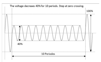
IEC61000-4-11 Voltage dip
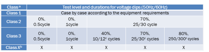
a Classes as per IEC61000-2-4; see Annex B.
b To be defined by product committee. For equipment connected directly or indirectly to the public network, the levels must be less severe than Class 2.
c “25/30 cycles” means “25 cycles for 50Hz test” and “30 cycles for 60Hz test”
Simulation setup procedure
First, determine the exam level and duration.
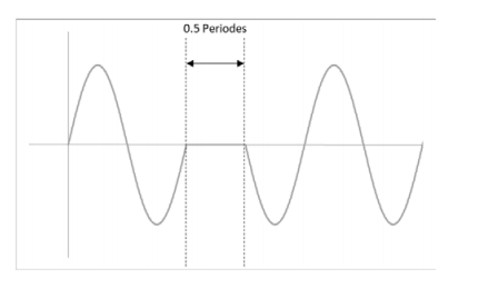
Let’s create a simulation waveform of 0.5 cycle with 0% voltage amplitude of Class 2. (As an example, the test voltage and frequency are 120V 60Hz.)
The duration is 0.5 cycle, so it is 8.3ms (= 0.5/60Hz). The test level is 0%, so it is 0V.
Next, set the simulation function.
1. Set the steady-state voltage and frequency. (ex. 120V 60Hz)
2. Press SIM>COND(F4) to set the conditions.
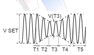
3. POL ”+” / T1 TYPE “TIME” / T5 TYPE “TIME”
4. Press ESC to return to the previous screen.
5. Press EDIT(F5) to set the parameters.
6. T1 ”0” / T2 “0” / T3 “10ms“ / T4 “0” / T5 “10s” / T3 VOLT “0”
7. Press ESC to return to the previous screen.
8. Select LOOP(F3) to set the number of repetitions. (ex. 3 times) Configuration is complete.
Press SIM > RUN (F1) to execute a power line disturbance simulation.
Using a trigger out signal makes it easier to observe the waveform with an oscilloscope.
Products Mentioned In This Article:
- PCR-WE Series please see HERE