 FREE SHIPPING £75+
  CELEBRATING 50+ YEARS
  PRICE MATCH GUARANTEE

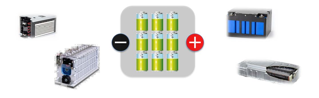
With the recent diversification of battery module application such as for automotive and backup, more and more users want to conduct a battery module charge-discharge test, besides of an individual cell battery test.
As a battery management system has been greatly developed to maximize battery’s capacity, the practical needs to perform evaluations on balancing battery charge-discharge are increased. Here you will find the method to balance the battery charge-discharge by using our DC power supply and electronic load.
Unbalancing Battery Module Charge
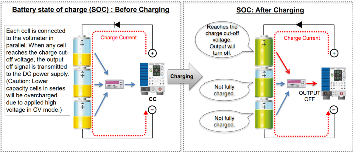
CC flows into each cell with different capacity and SOC unbalance. Cells with less charge capacity always reach the charge cut-off voltage faster. → The battery module cannot reach its full capacity.
Unbalancing Battery Module Discharge
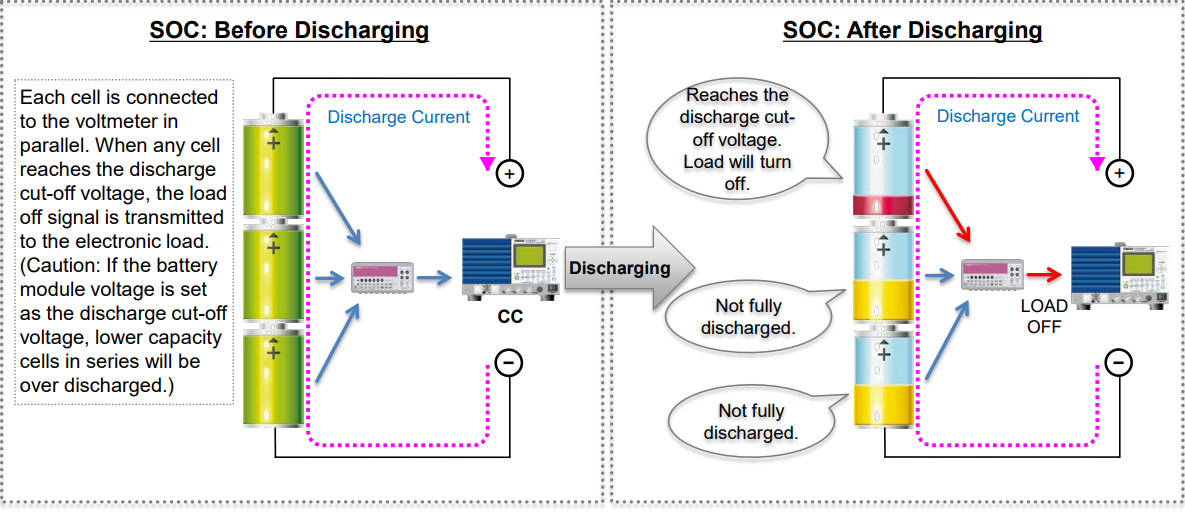
CC is sunk from each cell with different capacity and SOC unbalance. Cells with less discharge capacity always reach the discharge cut-off voltage faster. → The battery module cannot be fully discharged.
Balancing Battery Module Charge-Discharge
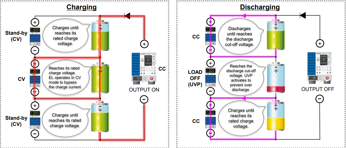
Electronic loads are separately connected to each cell in parallel to perform the balancing charge-discharge.
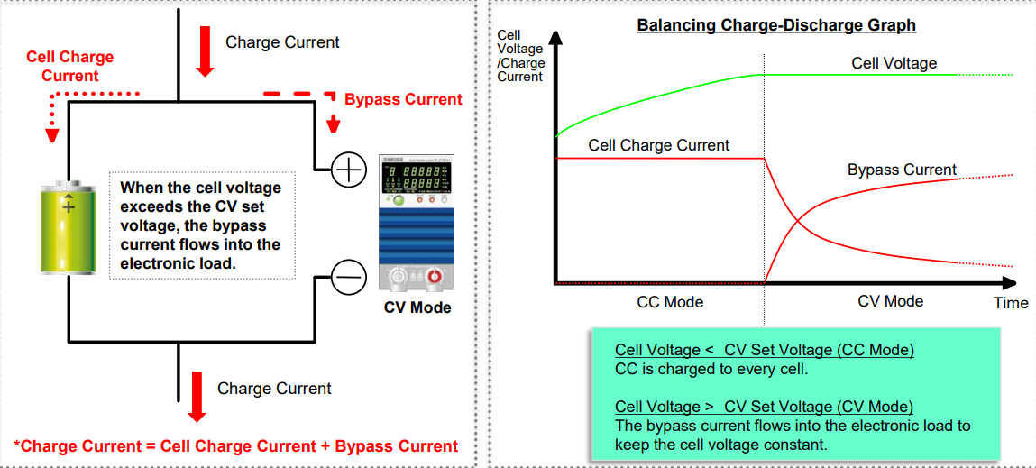
Balancing Battery Module Charge
Electric loads connected to each cell in parallel operate in CV mode.
Balancing and optimal charge to series cells is available by performing the CC-CV charge; The CC setting is set to a DC power supply and the CV setting is set to electronic loads.
Note: 1) The CC limit for electronic loads should be set higher than the charge current. 2) The electronic load alarm should be linked to the power supply output.
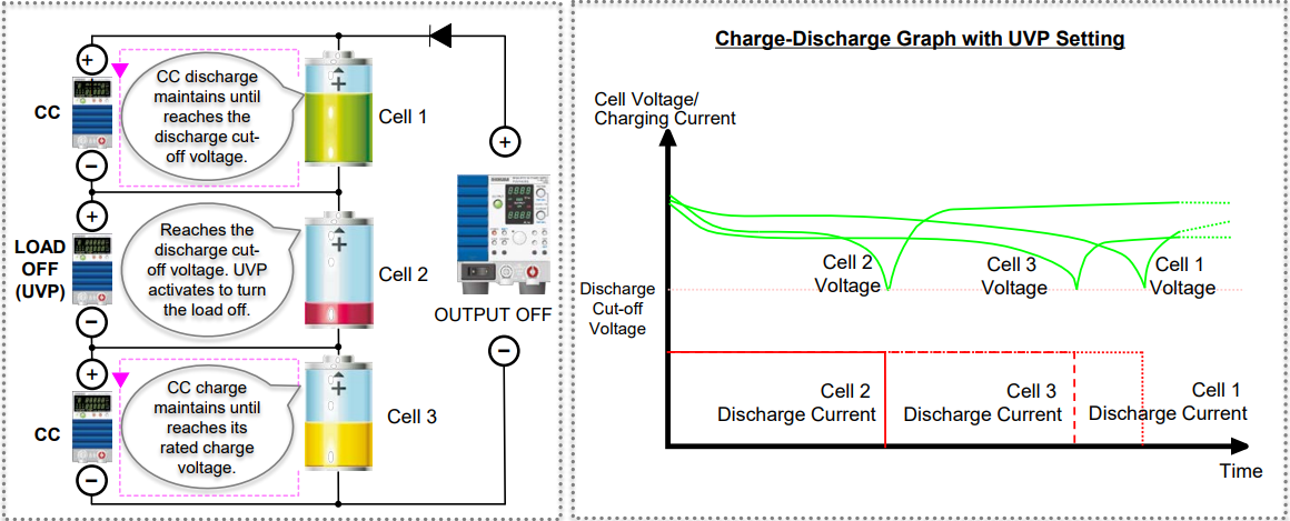
Balancing Battery Module Discharge
Electric loads connected to each cell in parallel operate in CC mode independently.
To stop the discharge; 1) Set the discharge cut-off voltage as under voltage protection (UVP) to turn the load off. 2) Set the discharge cut-off voltage as the CV set value to perform the CC+CV operation. Note: 1) The negative input terminal in each electronic load should be isolated. 2) With the external analogue control, the control signal terminal should be isolated.
Products Mentioned In This Article:
- DC Power Supplies & Electronic Loads please click HERE