 FREE SHIPPING £75+
 CELEBRATING 50+ YEARS
 PRICE MATCH GUARANTEE


When choosing a power supply to run a DC motor, the first and most important thing you need to consider is a maximum current that your motor will use. DC motor typically requires a startup current which is quite a lot higher than its running current. Due to this, not all DC power supplies can provide sufficient power to DC motors.
In this white paper, we will take a look at the capability of our bipolar DC power supply PBZ20-20A, which can supply a short-term peak current up to six times its rating current (± 120 Apk CV).
Below, we are going to share our measurement results that show how PBZ20-20A worked with a DC motor.
1. Purpose of Measurement
The purpose of this measurement is to determine the performance of PBZ20-20A on a brushed DC motor by measuring the voltage and current waveforms.
2. Wiring Connection
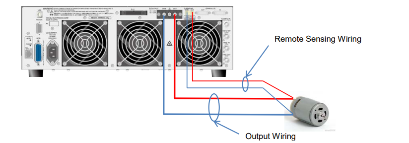
▪ Each was crimped: the positive ends and negative ends of output and remote sensing wires. ▪ Wiring length: Approx. 1 m for both remote sensing and output wiring
▪ Wiring cross section: Output wiring: AWG16 1.31 mm² (1.25 sq),
Remote sensing wiring:AWG24 0.205 mm² (0.2 sq)
▪ The twisted pair was made on the output and remote sensing wire. 3. Measurement Conditions
▪ Output mode: CV mode
▪ Response setting: CV mode voltage response: 3.5 μs/100 μs, CC mode current response: 35 μs/1 ms * PBZ20-20A can output a peak current only when the current response is set to 1 microsecond in CV
mode.
▪ Limit setting: Voltage limit: + 14 V (protect the motor from overvoltage),
Current limit: ± 22 A (output current setting: max.)
▪ Voltage setting: 12 Vdc
▪ Motor to be used: Brushed DC motor – details unknown.
4. Results
1) Response setting: CV 3.5 μs, CC 35 μs
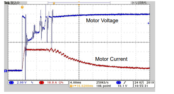
▪ The motor voltage was oscillated because the output current was limited (no peak current was provided).
2) Response setting: CV 100 μs, CC 1ms
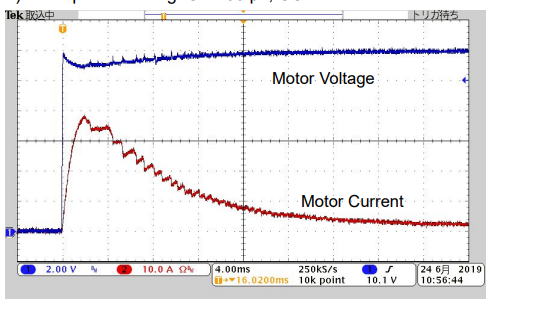
▪ CV mode voltage response setting was changed: 3.5 μs to 100 μs. ▪ CC mode current response setting was changed: 35 μs to 1 ms.
▪ Since the current response was set to 1 microsecond, PBZ20-20A could output the peak current. ▪ The voltage oscillation was reduced.
3) Response setting: CV 100 μs, CC 1ms with remote sensing turned on
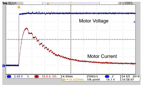
▪ With the remote sensing turned on, the voltage became more stable.
4) When the output was turned off:
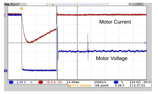
▪ When the output was turned off, the followings happened;
1) The reverse motor current was generated and then interrupted. It took approx. 10 microseconds.
2) The motor voltage started to rise.
3) The overvoltage protection (OVP ALM) was activated.
The reason why this happened was because the PBZ20-20A’s relay contact was suddenly opened (disconnected).
5) Extended view of No. 4
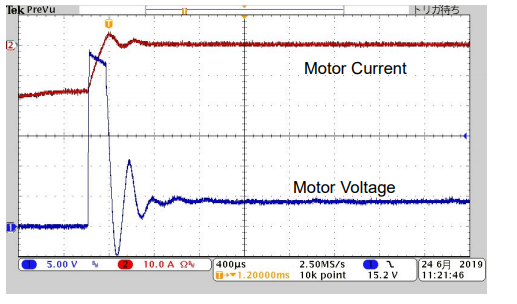
▪ The motor voltage reached approx. 28 Vdc max.
6) When the motor voltage was changed from 12 Vdc to 0 Vdc by the sequence control:
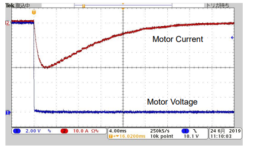
▪ The voltage rising was not found under the sequence control.
7) After the output was turned off:
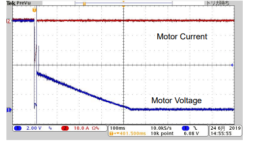
▪ Until the motor was fully stopped, the motor reverse voltage had been applied to PBZ20-20A.
▪ The voltage detection circuit in PBZ20-20A kept closed (connected) even when the output was turned off. This could be a small path to allow a little bit of motor reverse current (discharging current) to flow back to PBZ20-20A.
5. Measurement Summary
▪ When the PBZ20-20A’s output was turned off, the brushed DC motor started functioning like a generator inverting the direction of its current and forcing it into PBZ20-20A.
▪ As an explanation of measurement No. 4; when the output was turned off, the reverse current flew for approx. 10 microseconds. However, the output relay contact in PBZ20-20A was open, so there was no path for the current to flow. This sudden release of energy induced the transient voltage spike.
▪ PBZ20-20A provided the peak current at 45 A for the brushed DC motor. The duration that the output current exceeded 20 A was approx. 8 microseconds.
6. Recommendation
▪ Bipolar power supply can sink a reverse current, while DC power supply cannot. If using a DC power supply and motor, connect an electronic load in parallel to absorb a reverse current.
▪ To protect PBZ20-20A from an overvoltage, wait until an output current reaches 0 A before turning an output off.
7. Conclusion
The above measurement results prove that PBZ20-20A can meet the requirement to run the DC motor to be tested. To identify whether PBZ20-20A can sufficiently power your DC motor or not, we recommend that you carefully read the data sheets or check the specifications.
Products Mentioned In This Article:
- PBZ Series please see HERE