 FREE SHIPPING £75+
 CELEBRATING 50+ YEARS
 PRICE MATCH GUARANTEE


As described in Part 1, electronic loads can act as a variable resistor and regulate a current depending on your applications. With this function, electronic loads can be used as substitute for high-power components. To fulfill this function and test DUTs effectively, there are four operation modes for electronic loads: 1) constant current 2) constant resistance 3) constant voltage and 4) constant power. Part 2 and Part 3 will describe each of these modes and the sequence function to simulate the specific electric and electronic components.
2-1. Constant Current (CC) Mode
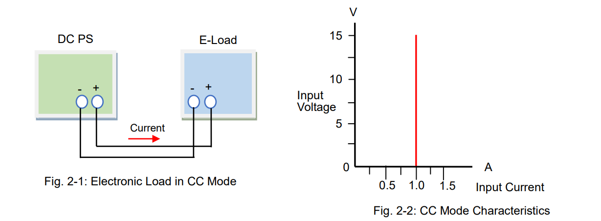
In CC mode, an electronic load consumes constant current in regardless of input voltage variations. Figure 2-1 shows the connection diagram between the DC power supply and electronic load. Figure 2-2 shows the input current – input voltage characteristics in CC mode. You can see that the current is constant all throughout despite changes in voltage.
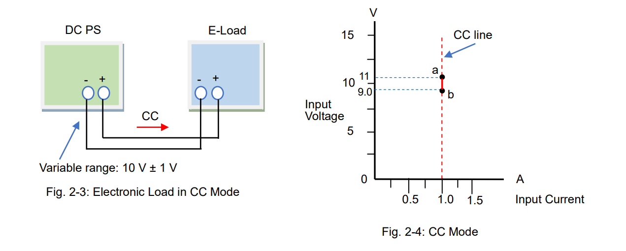
For example, if your test power supply has the output voltage variable range of 10 V ± 1 V, and its rated output current is 1 A, you need to determine whether it can provide 1 A with its output voltage change from 9 to 11 V. So you should prepare an electronic load that constantly consumes the current of 1 A regardless of the input voltage changes from 9 to 11 V.
Figure 2-3 shows the connection diagram. Figure 2-4 shows that the electronic load operates the CC mode regardless of the input voltage changes from 9 to 11 V.
You can also let the electronic load behave as a variable resistor (see also Part 1, Sec. 1-2-1: “Act as Variable Resistor”) but you will need to change the resistance value of the electronic load each time the input voltage changes. This is not efficient because you need to set the resistance and monitor the current all the time. Figure 2-6 shows that the electronic load consumes the current of 1 A by varying the resistance value.
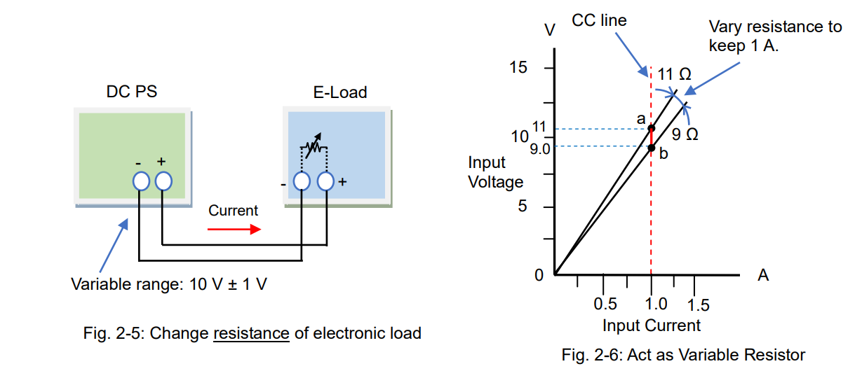
Compared to this method, the CC mode allows you to easily vary the current to flow. The CC operation is intuitive and used for diverse applications.
By the way, what is an operating principle of the CC mode? As stated in Part 1, electronic loads can provide various operations depending on the circuit functions. In CC mode, electronic loads will automatically adjust the resistance value, just like the way of Figure 2-6, to maintain the constant current. In more detail, electronic loads will monitor the current; when the voltage rises, it increases the resistance with reducing the current flow, and vice versa, when the voltage falls, it decreases the resistance to prevent the current from falling.
Operating Principle
Figure 2-7 shows the operating principle diagram of the CC mode. The error amplifier internally controls the current regulator (equivalent to the resistance value) that compares the set current (I) and actual input current detected by the current detector to make them equal. So, the electronic load can constantly absorb the set current (I) by using the feedback control, which is quite popular method in power supplies.
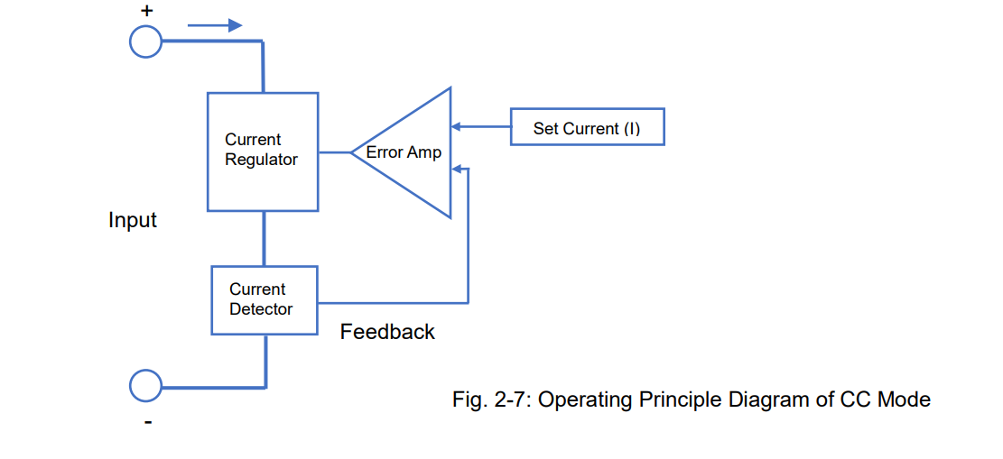
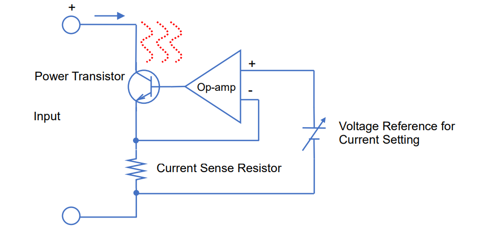
The current regulator in Figure 2-7 controls the current flow. The electronic load circuits have elements such as a transistor or FET rather than a resistance element (see figure 2-6), because they are more electronically easy to control. Figure 2-8 shows the circuit diagram example of the CC mode. In the circuit, the operational amplifier controls the power transistor to make the voltage across the current sense resistor equal to the voltage reference for current setting, so that this circuit enables the CC mode.
The voltage is applied to the electronic load to sink the current. This applied energy is transformed into a heat by the power transistor or power FET so the electronic loads often have a cooling fan.
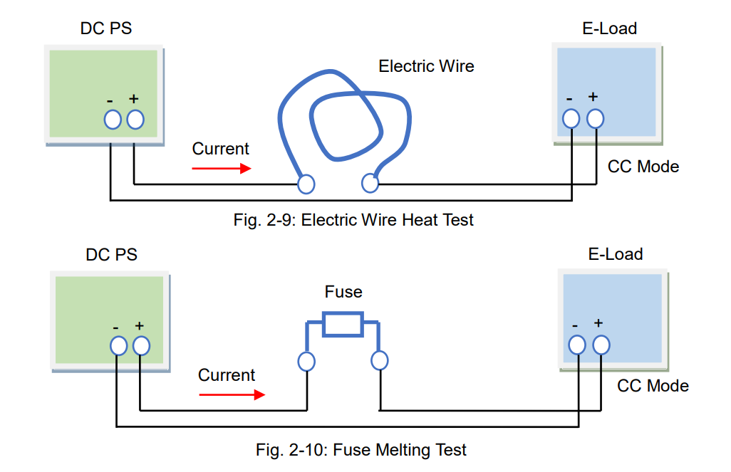
Example Applications for CC Mode – Electric Wire Heat Test and Fuse Melting Test
As a part of the power supply testing, a load regulation test and line regulation test will be performed by the CC mode of electronic loads. During these tests, the output voltage from the power supply will vary within its maximum ratings so the CC mode is suitable for these tests. The other example applications for the line regulation test (CV test) are an electric wire heat test (fig. 2-9) and a fuse melting test (fig. 2-10). The wire resistance and fuse resistance will change significantly when the current flows through them. To sink a constant current from the test samples, use the CC mode of electronic loads.
2-2. Constant Resistance (CR) Mode
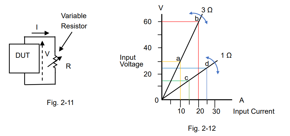
The CR mode is a mode that electronic load act as a base component, variable resistor (see also Part 1, Sec. 1-2-1: “Act as Variable Resistor”). When an electronic load has a resistance characteristic like figure 2-11 and 2-12, it operates in CR mode. As shown in figure 2-12, you can adjust the resistance value such as 1 Ω or 3 Ω during the CR mode.
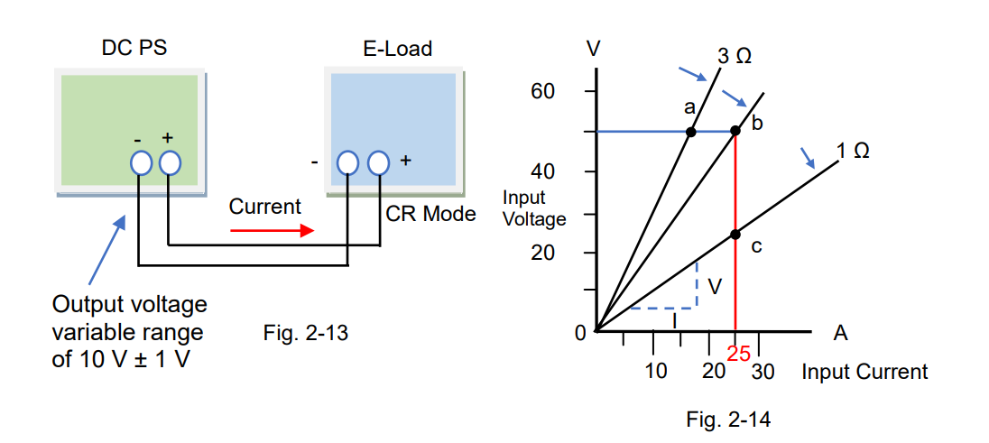
The CR mode is suitable for various applications. It is useful that electronic loads act as a large-capacity variable resistor. One of the typical applications is to test the current limiting characteristic of DC power supplies.
Figure 2-13 shows the connection diagram between the DC power supply and electronic load. The blue straight line in figure 2-14 shows the range that the power supply operates in CV mode. Point ‘a’ shows that the input voltage of electronic load is 50 V with the resistance of 3 Ω. The input voltage moves along this blue line in according with the resistance variations. If the resistance decreases and the input voltage will reach point ‘b’, then the voltage moves along the red line. When the resistance turns to 1 Ω, the input voltage will reach point ‘c’. While the input current is on the red line, the output current from power supply is regulated by 25 A.
The CR mode is also constructed in the circuit functions of electronic loads. The resistance (R) is calculated by R = V/I. In figure 2-14, the resistance is the slopes.
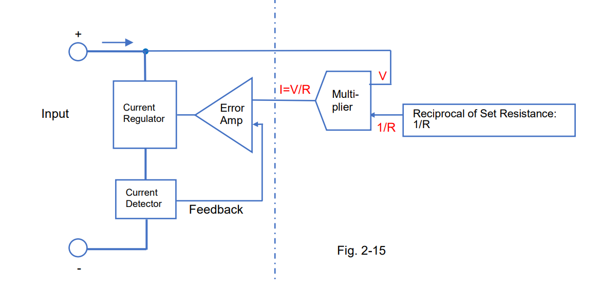
Operating Principle
Figure 2-15 shows the operating principle diagram of the CR mode. The left side of the diagram is the same as shown in figure 2-7 and the right side shows the component to be used for the CR mode. The multiplier will multiply the input voltage (V) by the reciprocal of set reference (1/R), so the multiplier will output V/R. It equals to ‘V/R = I’, so when V is applied the current will flow according to ‘I = V/R’. That is, the set reference R (= V/I) is constant and this circuit operates in CR mode based on R. The figure below uses the reciprocal of set resistance (1/R), so you adjust it by R. 1/R is conductance G (in Siemens S).
For the current regulator, a power transistor or power FET are usually used.
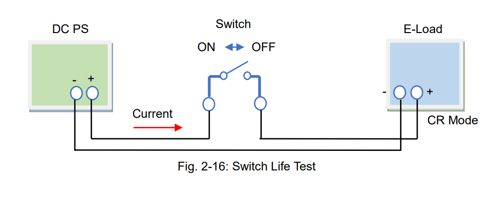
Example Applications for CR Mode – Switch Life Test
The example application for the CR mode is the switch life test. Figure 2-16 shows the test system that the switch is placed between the DC power supply and electronic load to repeat the on-off switching tests. Excellent test-reproducibility can be achieved from this system because the CR operation avoids the rapid current on-off switching.
(Note: The current rise time differs depending on the electronic load performance.)
Products Mentioned In This Article:
- Kikusui Electronic Loads please see HERE