FREE SHIPPING £75+
 CELEBRATING 50+ YEARS
 PRICE MATCH GUARANTEE


Continuing from the previous white paper, here are three more effective applications and examples of electronic loads.
6-1. Applying the Load to a Motor
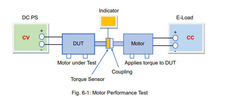
Figure 6-1 shows a block diagram illustrating an example of the DC motor test system.
In this system, the test motor (DUT) is driven by the DC power supply. The coupling is connected to the DUT and another motor in order to apply torque to the DUT. The torque sensor is placed between the DUT and coupling in order to measure the torque and rotation speed. The electronic load is connected to the motor to draw the current.
If the motor’s current in increased by the load while operating the DUT, the DUT’s motor torque will also increase. So, the electronic load adjusts the torque applied to the motor in order to obtain the T-N characteristics: the relationship between the rotation speed and torque.
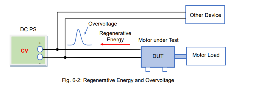
6-2. Absorbing the Motor Regenerative Current
Reverse voltage is generated and returned to a power source by reversing the direction of the motor. Batteries can absorb this regenerative energy, but typical DC power supplies*1 cannot. So, the overvoltage may flow to the output terminal of a DC power supply. This activates an overvoltage protection in the DC power supply, but this overvoltage may reach other devices on the same test system.
*1: A bipolar DC power supply can absorb regenerative power like a battery.
To prevent this, set the electronic load to the constant voltage (CV) mode as described in Part 3, Sec.3-1 or, set it to the constant current (CC) mode as described in figure 6-3 blow. In figure 6-3, the DC power supply and electronic load are connected in parallel. The electronic load operates in CC mode and this CC current should be set to exceed the DUT’s regenerative current. When the current (Io) flows from the DC power supply, the electronic load draws ‘Io’ and converts in into ‘Icc’. And when the test motor (DUT) is driven, the motor current (Im) is fed into the DUT. Therefore, Io = Icc + Im.
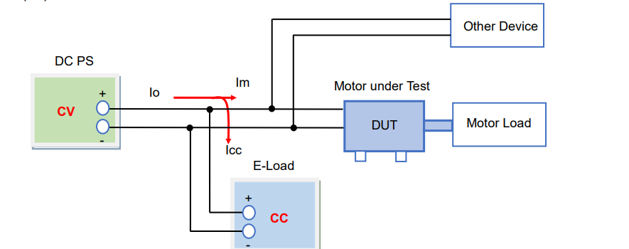
Figure 6-4 shows how the DUT regenerates the current to the DC power supply. During power regeneration the motor regenerative current’s (Irev) direction reverses and flows into the electronic load. However, the electronic load works to keep its current (Icc) constant. Therefore, Icc = Io + Irev. When ‘Irev’ increases, the DC power supply current (Io) decreases, and vice versa (‘Irev’ decreases = ‘Io’ increases).
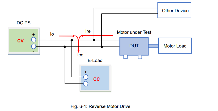
This system is more effective for preventing overvoltage than clipping the voltage with the CV setting, but it consumes more power.
6-3. Building a Mid-Speed CV Power Supply System
The voltage rising and falling time of typical DC power supplies exceeds 10 milliseconds (ms), but high-speed DC power supplies limit it to 3 micro seconds (µs).
Instead of buying a high-speed power supply model, you can build a mid-speed CV power supply system (Tr/Tf: 100 μs to a few ms) by combining your own DC power supply with an electronic load. Let’s look at the two examples below.
1. Mid-Speed CV Power Supply System (1)
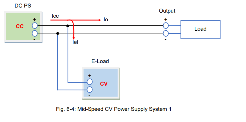
In figure 6-4, the DC power supply and electronic load are connected in parallel. For the DC power supply, set the CC value to more than the maximum current that the load uses. The electronic load maintains a CV set voltage, and you can adjust it using your PC.
Under the no-load condition, the output current from the DC power supply (Icc) all flows into the electronic load.
With the load-on condition activated, the load current (Io) is fed into the load by reducing the flow of the E-load current (Iel). Therefore, Icc = Io + Iel.
If you use a series regulator power supply, the response time could take a few milliseconds. For typical switching power supplies, the response time takes more than 10 milliseconds. However, this depends on how quickly the electronic load activates the CV mode, so you need to verify the actual time.
Note: this system can maintain speed even with capacitive loads because the electronic load can sink (absorb) current from the load. The regenerative current of the motor mentioned above can be absorbed.
2. Mid-Speed CV Power Supply System (2)
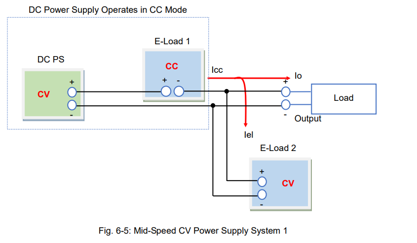
The system, as shown in figure 6-5, is faster than the system shown in figure 6-4, achieving about 100 microseconds.
In figure 6-5, the DC power supply and electronic load are connected in series to allow the DC power supply to operate in CC mode. The operation of this DC power supply is the same as the one shown in figure 6-4. For electronic load 1, set the CC value above the maximum current that the load uses. Since electronic load 2 operates in CV mode, it maintains a CV set voltage and you can adjust it with your PC.
Under the no-load condition, the output current from load 1 (Icc) all flows into load 2.
With the load-on condition, the load current (Io) is fed into the load by reducing the flow of the electronic load current (Iel). Therefore, Icc = Io + Iel.
The reason this system is faster is because the CC mode operation of load 1 is exceptionally fast (approx. 50 microseconds faster).
DC Power Supply Operates in CC Mode