Free Shipping logo FREE SHIPPING £75+
50 years of Telonic Instruments Ltd logo CELEBRATING 50+ YEARS
Price Match logo PRICE MATCH GUARANTEE

Update Firmware on the MSO5000 & DS7000 Series Digital Oscilloscope

Posted on: December 16th, 2020 by Doug Lovell

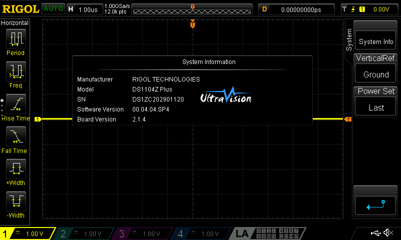
To update the firmware push the keypad Utility key followed by System at the bottom right corner of the display:


Now push Help:


You now have the option of updating firmware using a USB memory stick by selecting “Local upgrade” or if you are connected to the LAN online upgrade can be selected.

How to use the MSO5000, DS7000 and MSO8000 Logic Analyzer different capabilities

Posted on: December 16th, 2020 by Doug Lovell

The logic analyzer allows you to view up to 16 digital channels at once along with group them and label them to make your measurements easier to view.

  • To activate the logic analyzer, press the “LA” button or the “L” section at the bottom of the display.  Note that the LA channels will allow you some vertical scaling control within the LA menu, but the horizontal scaling is controlled through the horizontal control knobs.
  • Once you have entered the logic analyzer menu you can choose which channels you would like to turn on by pressing the “On/Off” section and then with in there you can either turn on or off each bank of eight channel or you can turn on or off specific channels.  Turn “OFF” channels “D15-D8”
  • This is also where you can group your channels together by pressing “Group” and then you can select one of the four groups and then you can select which channels you would like to group together.  Group channels D0-D2 together, and then choose another group and group D5-D7 together.
  • Then press “Back” and then press “Group On/Off” to turn on both groups.
  • Press the “Back” button.
  • To change the channel arrangement, press “Arrange”.  Notice how this will change how the channels will be positioned on the display either from D0-D7 or D7-D0.
  • To change the vertical scaling of the channel press “Size” and then select “Large as your desired size.  This will then fill the entire display with the eight channels.
  • Press “Label” and then turn “Display” ON. You will now see the channel labels being displayed on the left-hand side of the display, and you can also change these labels.  To change the labels press “Select” and choose your channel, then you can select a predefined label from the “Library” or you can create your own custom label by pressing “Label” and then you type one in with the onscreen keyboard.
  • Add a “CLK” label to channel “D0” and then label “D7” with your name.

Inverted color printing with the Rigol DS2000/A, DS4000, and DS6000 Oscilloscopes

Posted on: December 16th, 2020 by Doug Lovell

The DS series of oscilloscopes can save display images directly to an external USB memory device using the Quick Print feature.

This can be extremely helpful in documenting the input waveforms as well as the instrument settings and any measurements that may be active on the display. 

There are a number of print settings that can change the wave generation combining uncompromised performance with unprecedented value. 
 
1.    To access the print menu, press UTILITY > Down Arrow > Print 


2.    The Print Utility page 1 has Color Palette menu selection. Color will use the standard colors used on the physical display for the saved images and Greyscale will use only grey colors for the saved image. 
 
3.    The Print Utility page 2 has Invert menu selection. ON will invert every color. OFF will use the standard color selection.  
      
4.    Use the Quick Print button to quickly save display images to the external USB drive: 
 
 
Here are examples of the different settings: 
 
  
             Palette = Color, Invert = OFF 
 

            Palette = Grey Scale, Invert = OFF 
 
  
            Palette = Color, Invert = ON 
  

            Palette = Grey Scale, Invert = ON

DS1000Z Counter Technical Details

Posted on: December 16th, 2020 by Doug Lovell

Basic specifications:
 
– Counter sampling rate is fixed at 250 MSa/sec
– Hysteresis level (defined further below) is ~1 division on the smallest vertical ranges (< 5 mV) and about 0.3 divisions (with Noise Reject Off) ir 0.7 divisions (with Noise Reject on) in higher vertical scales (>- 5mV).
 
Further Details:
 
DS1000Z digitize the sampling data, and using Hysteresis comparator to make the trigger stable


Schematic diagram of DS1000Z Hysteresis comparator when using rising edge trigger
 
1. The red part won’t be counted when using hysteresis comparator, because it doesn’t achieve the range.
2. The triangle in the diagram is the sampling data after digitization, we can see it by setting dot type in display menu.
3.The sample rate of DS1000Z counter is 250MSa/s (this is same with different model). When higher speed input signal is connected, the ‘peak’ may not achieve the range of hysteresis or the signal may be too undersampled to be properly measured, so the counter’s value can be incorrect.
4. The range of hysteresis will change with vertical scale, so when input a low signal, we need to set the vertical scale lower for best results.
5. It’s also important to adjust the trigger level to the middle of the signal so that more ‘peaks’ can be counted beyond the hysteresis level.
 
Examples using dots display mode for clarity:

Input:50MHz/500mVpp sine wave,Vertical Scale:100mV,Trigger Level:0V 


Input:50MHz/500mVpp sine wave,Vertical Scale:500mV,Trigger Level:0V


Input:50MHz/200mVpp sine wave,Vertical Scale:100mV,Trigger Level:0V


Input:50MHz/125mVpp sine wave,Vertical Scale:100mV,Trigger Level:0V


Input:50MHz/110mVpp,Vertical Scale:100mV,Trigger Level:0V,AUTO

High speed distortion in vector mode:


The high speed signal will distortion with 250MSa/s sample rate


The Frequency measurement in the measurement menu for each channel is software based, but can sometimes be more accurate because it utilizes the displayed data to make the calculation. The displayed data can be up to 1 GSa/sec making some high frequency measurements easier.

Direct waveform transfer from a DS1000Z scope to a DG4000 generator

Posted on: December 16th, 2020 by Doug Lovell

The advent of digital storage oscilloscopes and arbitrary waveform generators has significantly improved troubleshooting electrical designs and systems.

A troublesome signal can be captured by the digital oscilloscope and then replayed an arbitrary waveform generator. This can allow you to create and reuse “real world” signals in a repeatable way.

The brief idea is as follows:

1.    Use a digital scope to capture a waveform of interest
2.    Transfer the waveform file to an arbitrary waveform generator
3.    Use the arbitrary waveform generator to source the captured waveform

This technique allows you to then use the arbitrary waveform generator to adjust the output waveform parameters like amplitude or frequency, and deliver the new waveform to the device-under-test (DUT).
Traditionally, the waveform data would be saved as a CSV formatted file, saved to a USB memory stick, formatted and edited to fit the arbitrary waveform generator file requirements, and then transferred to the arbitrary waveform generator for direct use on the DUT.

The Rigol DS1000Z series of oscilloscopes and the DG4000 series of Arbitrary Waveform Generators can perform this task even more quickly using a simple direct connection using a USB cable. With a few simple steps, you can transfer the waveform directly to the DG4000.. and even perform some edits on the waveform.

Requirements:

•    Rigol DS1000Z Series Oscilloscope (firmware revision 00.04.03SP1 or later)
•    Rigol DG4000 Series Oscilloscope (firmware revision 00.01.12 or later)
•       Rigol USB cable with RF chokes (shown below)

NOTE: You can request the latest firmware revision by contacting your local Rigol office or checking the regional Rigol website (www.rigolna.com for North America)

Setup:

1.    Power on both instruments

2.    Insert the large flat end of the USB cable into the front panel USB input of the arbitrary waveform generator and insert the other end of the cable into the rear panel USB input (labelled USB Device) of the oscilloscope as shown below:


Figure 1: USB connection to DG4000 series generator


Figure 2: USB connection to DS1000Z series scope

3.    Configure the oscilloscope to capture the signal of interest

NOTE: You can use the RUN/STOP button or SINGLE trigger mode to isolate a single waveform and prevent additional waveforms from triggering the scope.

4.    Press the ARB button on the DG4000 to activate the arbitrary waveform function

5.    Press the Down Arrow to access page 2 of the ARB menu

6.    Press SELECT WFORM

7.    Press STORED WFORMS

8.    The DS1000Z should appear as an option under DISK

9.    Set BROWSER to DIR and navigate to the DS1000Z using the scroll wheel. The active channels on the scope should appear as ON in the File Name

10.    Set BROWSER to FILE and navigate to the scope channel you want to copy

11.    Press READ to transfer the waveform from the scope to the generator

12.    The display of the generator should now show the captured waveform. You can use the arbitrary waveform settings to adjust the parameters (FREQ, AMPL) of the waveform.

13.    You can use the oscilloscope to confirm that the output is correct for your application. Connect the output of the DG4000 to the input of the scope and enable the output channel.

Figure 3: The DG4000 waveform (yellow) vs. the original waveform (white)

Save the waveform to nonvolatile memory:

The active arbitrary waveform being used by the DG4000 is actually located in the volatile buffer, and is only temporarily stored in the instrument. You can transfer the arbitrary waveform to one of the nonvolatile locations in the DG4000 internal memory for use later or you can save it to an external USB drive for later use.

1.    Press STORE > Set FILE TYPE to ARB FILE

2.    Select an ARB location and press SAVE

3.    Name the file and save by using the scroll wheel to highlight the character of interest and then press SELECT to enter the character

4.    When you are finished naming the file, press SAVE to store the file to nonvolatile memory

MSO8000, DS7000 and the MSO5000 Arbitrary Waveform Generator

Posted on: December 16th, 2020 by Doug Lovell

The signal generator allows you to both create standard waveforms but also allows you to easily create some custom waveforms as well as replicate a captured signal on the oscilloscope.

  • To activate the logic analyzer, press either “GI” or “GII” on either the front panel of the instrument or at the bottom of the screen.
  • To begin with to select your desired waveform press “Wave” and then you can select form several different built in waveforms as well as load arbitrary waveforms that you either created externally or by copying one of the scope analog channels.
  • Within the waveform menu you can set the functions frequency, amplitude, offset, starting phase.
  • To modulate, burst or sweep the signal, you will need to press “Settings”, then “Type” and then select your desired advanced feature.


  • To create the signal below connect “GI” to “Channel 1” on the instrument with a BNC cable.
  • Select “Sinc” as your waveform by pressing “Wave” and then “Sinc”.
  • Then change the signals frequency to 10 kHz.  You can do this by either pressing on “Frequency” on the touch screen and then using the pop-up number pad or you can use the keys and then use the intensity knob to change the frequency settings.
  • Press “AUTO” and you will see an image like the one below.


(The signal generator on the front of the MSO5000 and the DS7000 is a optional accessory, to activate them you will need to install a license.)

DS1000Z noise performance

Posted on: December 16th, 2020 by Doug Lovell

Here are a few screen captures of a DS1104Z series oscilloscope with various inputs. The intent is to show the basic noise you can expect from a similar instrument.


Figure 1: DS1104Z with open input, 10mV/div vertical scale, 1us/div horizontal scale.


Figure 2: DS1104Z with 10x probe connected to probe compensation point. 500mV/div vertical scale, 200us/div horizontal scale.


Figure 3: DS1104Z with 10x probe connected to probe compensation point. Zoomed to 10mV/div vertical scale, 200us/div horizontal scale.


Figure 4: DS1104Z with 1V DC input. Direct connection to function generator with coaxial cable. 10mV/div vertical scale, 200us/div horizontal scale.

Unable to save CSV data on a DS1000Z series scope

Posted on: December 16th, 2020 by Doug Lovell

Comma Separated Values can be saved on a USB memory stick by going to the Storage menu and selecting CSV. If you are unable to save the file and see a “Function  Limited!” error displayed check that the scope has been triggered. 

For example, if the scope trigger mode is set to Normal and the Run/Stop keypad button is green the scope has not triggered and you will see Wait flashing on the upper left of the display. In this condition CSV data cannot be saved and you will see the error.

MSO5000, DS7000 and MSO8000 Alternative Factory Reset and Firmware Upgrade

Posted on: December 16th, 2020 by Doug Lovell

To reset or upgrading the firmware on the MSO5000, DS7000 and MSO8000 series of oscilloscope without using the instrument’s Utility menu:

1) Power cycle the instrument
2) During the boot sequence, quickly and repeatedly press the Single button in the upper right hand corner of the instrument.

MSO5000 series Open Source Acknowledgment

Posted on: December 16th, 2020 by Doug Lovell

RIGOL’s MSO5000 series product uses a number of open source software packages. This document lists the open source software packages used in MSO5000 series product.

https://beyondmeasure.rigoltech.com/acton/attachment/1579/f-79a90744-6878-4071-b9f1-ab4780ccf05b/1/-/-/-/-/MSO5000.pdf

MSO&DS7000/8000 series Open Source Acknowledgment

Posted on: December 16th, 2020 by Doug Lovell

RIGOL’s MSO&DS7000/8000 series product uses a number of open source software packages. This document lists the open source software packages used in MSO&DS7000/8000 series product.

https://beyondmeasure.rigoltech.com/acton/attachment/1579/f-232b8974-dafb-4d2e-9487-5d95f5c247a3/1/-/-/-/-/MSO_DS7000%268000.pdf

Service Action on DS1000Z and MSO1000Z

Posted on: December 16th, 2020 by Doug Lovell

We have become aware of a manufacturing issue that may impact the usability of your instrument.  If you are experiencing problems with your horizontal and vertical adjustment controls you likely need to download and install the latest firmware to address the issue.

First Check your SN Range.  If your instrument falls between the following serial number ranges your unit is likely affected and you should load the latest Firmware.

DS1ZA203514550 through DS1ZA204719916

DS1ZB203800381 through DS1ZB204400481

DS1ZC203601463 through DS1ZC204201813

DS1ZD203800906 through DS1ZD204401180

If your unit falls in these serial number ranges you should likely load the new firmware.  You should check your current instrument software level by selecting:

Utility => System => System Info

If you are at 00.04.04.SP4 you are at the latest level and should take no additional action.  That will look like this:


If your instrument is at anything lower than 00.04.04.SP4 you should download the new firmware by following the attached link and install at your convenience.

DS1000ZUpdate.zip

Review the Upgrade Instructions
Review the Release Notes

If you have any questions or concerns or concerns about this update feel free to contact our technical support team at 877-474-4651 (select option #2) or email us at help@rigol.com.

If you are not the end user of the equipment please forward to the appropriate person in your organization.

Thanks so much for choosing RIGOL.  We apologize for any inconvenience this action will cause you.