 FREE SHIPPING £75+
 CELEBRATING 50+ YEARS
 PRICE MATCH GUARANTEE


Description
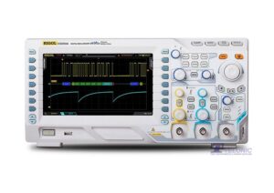
Rigol MSO8104 Mixed Signal Oscilloscope
The MSO8104 4CH, 1GHz, 10GSa/s Mixed Signal oscilloscope adopts RIGOL’s self-developed chipset “Phoenix”, which can gain the data acquisition capability of up to 10GSa/s sample rate, realising the high integration of all the function modules required for the analogue front-end (AFE), and greatly improving the consistency and reliability of the digital oscilloscope. The innovative UltraVision II technical platform is equipped with higher waveform capture rate, full digital trigger technology, and full memory hardware measurement technology. The MSO8000 series digital oscilloscope also integrates multiple instrument modules, such as MSO, arbitrary waveform generator, digital voltmeter, 6-digit counter and totaliser, and protocol analyser, offering extraordinary user experience at an unprecedented price point.
Features:
- Analogue bandwidth: 1GHz (Single-Channel and Half-Channel modes)
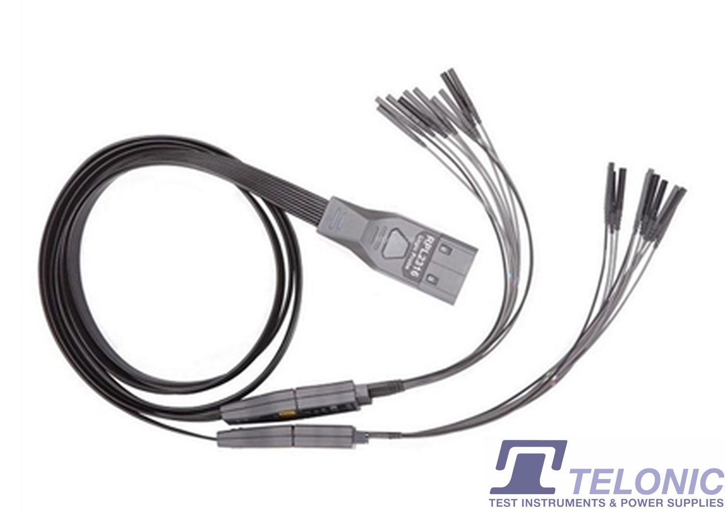
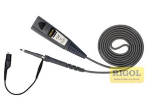
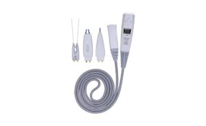
- 4 analogue channels, 1 EXT channel, and 16 standard configuration of digital channels (required to purchase the probe)
- Up to 10GSa/s real-time sample rate
- Up to 500Mpts memory depth (Standard)
- High waveform capture rate (Over 600,000 waveforms per second)
- Up to 450,000 frames of hardware real-time and ceaseless waveforms recording and playback functions
- Integrates 7 independent instruments into 1, including digital oscilloscope, 16-channel logic analyser, Spectrum analyser, arbitrary waveform generator (option), digital voltmeter, 6-digit frequency counter and totaliser, and protocol analyser (option)
- Auto measurement of 41 waveform parameters; full-memory hardware measurement function
- A variety of math operations, built-in enhanced FFT analysis, and peak search function
- Waveform histogram analysis (standard)
- Independent search, navigation keys, and event table
- Real-time eye diagram and jitter analysis software (option)
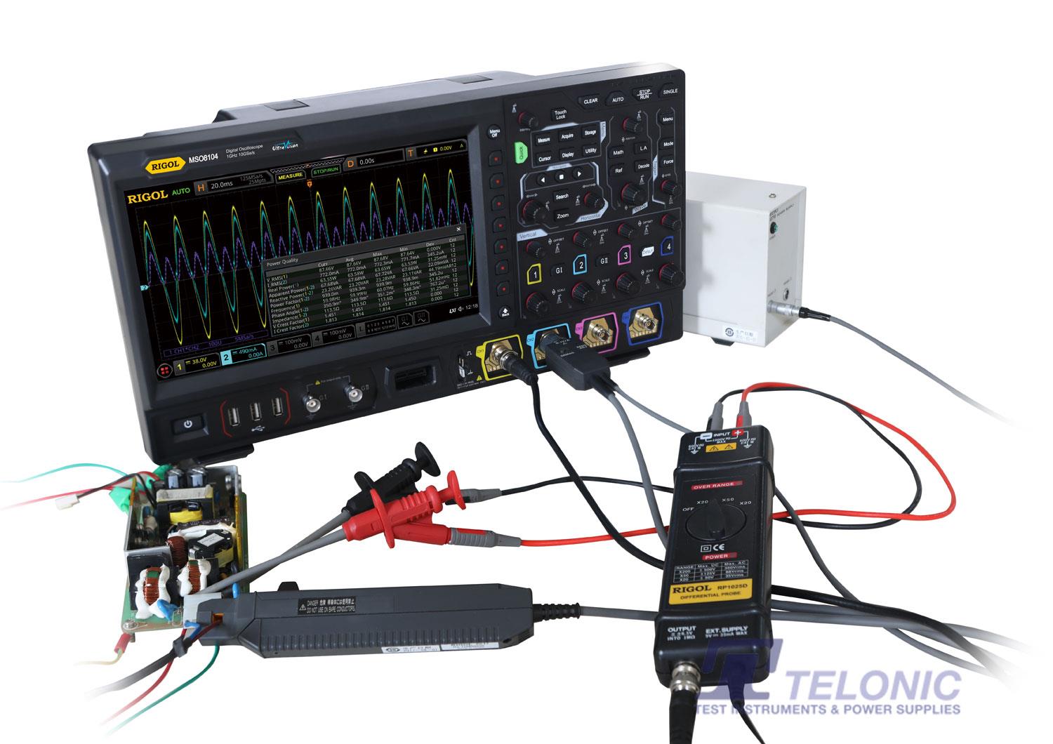
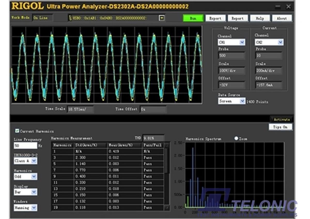
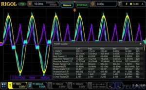
- Built-in advanced power analysis software (option)
- User-defined one-key quick operation
- 10.1-inch capacitive multi-touch screen, 256-level intensity grading display, with colour persistence
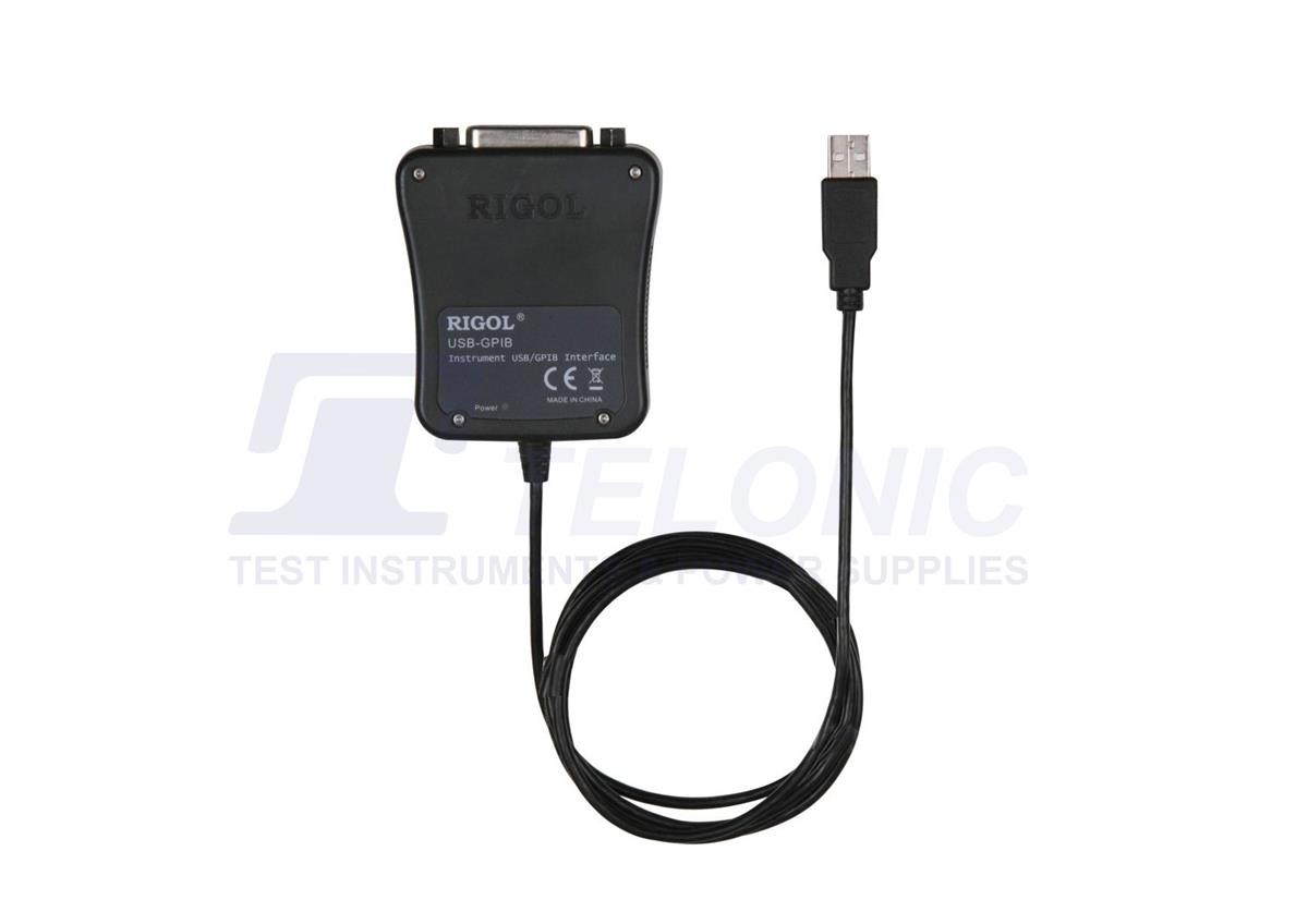
- Multiple interfaces available: USB HOST&DEVICE, LAN(LXI), HDMI, TRIG OUT, and USB-GPIB
- Web Control remote command
- Unique online version upgrade
- Sophisticated and convenient industrial design, easy to operate
Rigol MSO8000 Oscilloscope Comparison Table
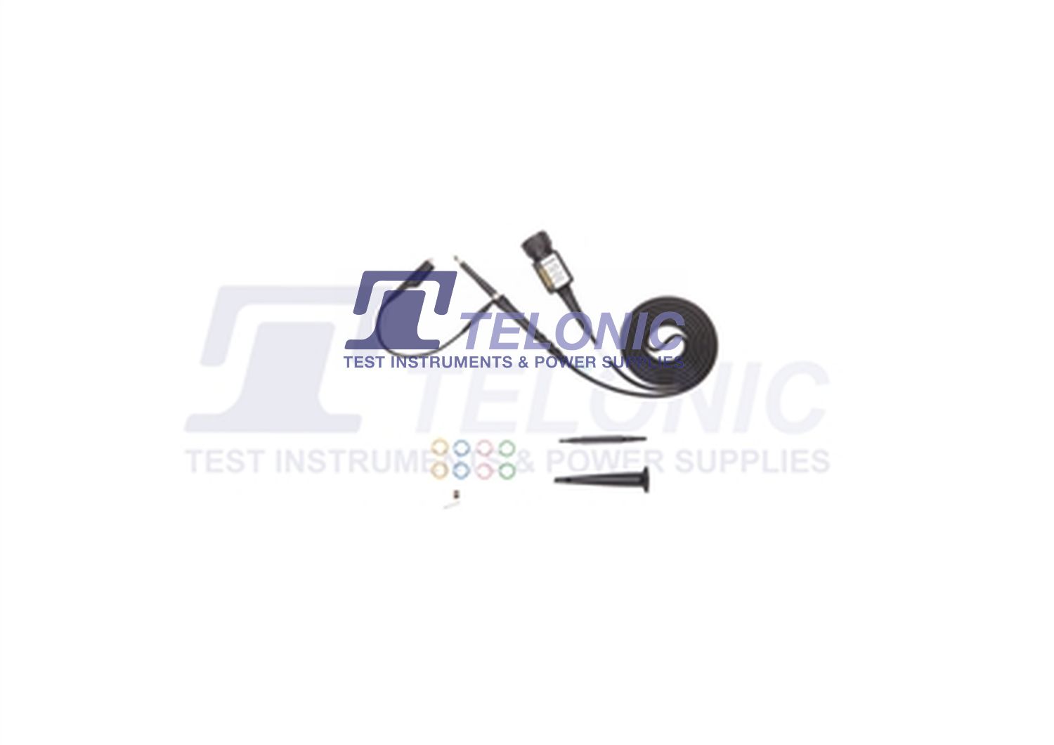
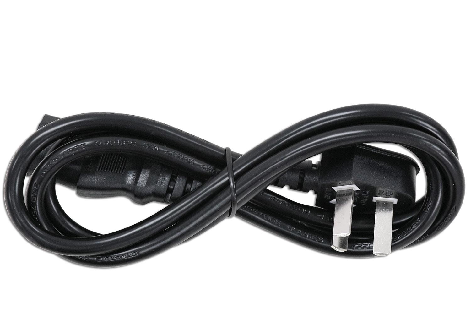
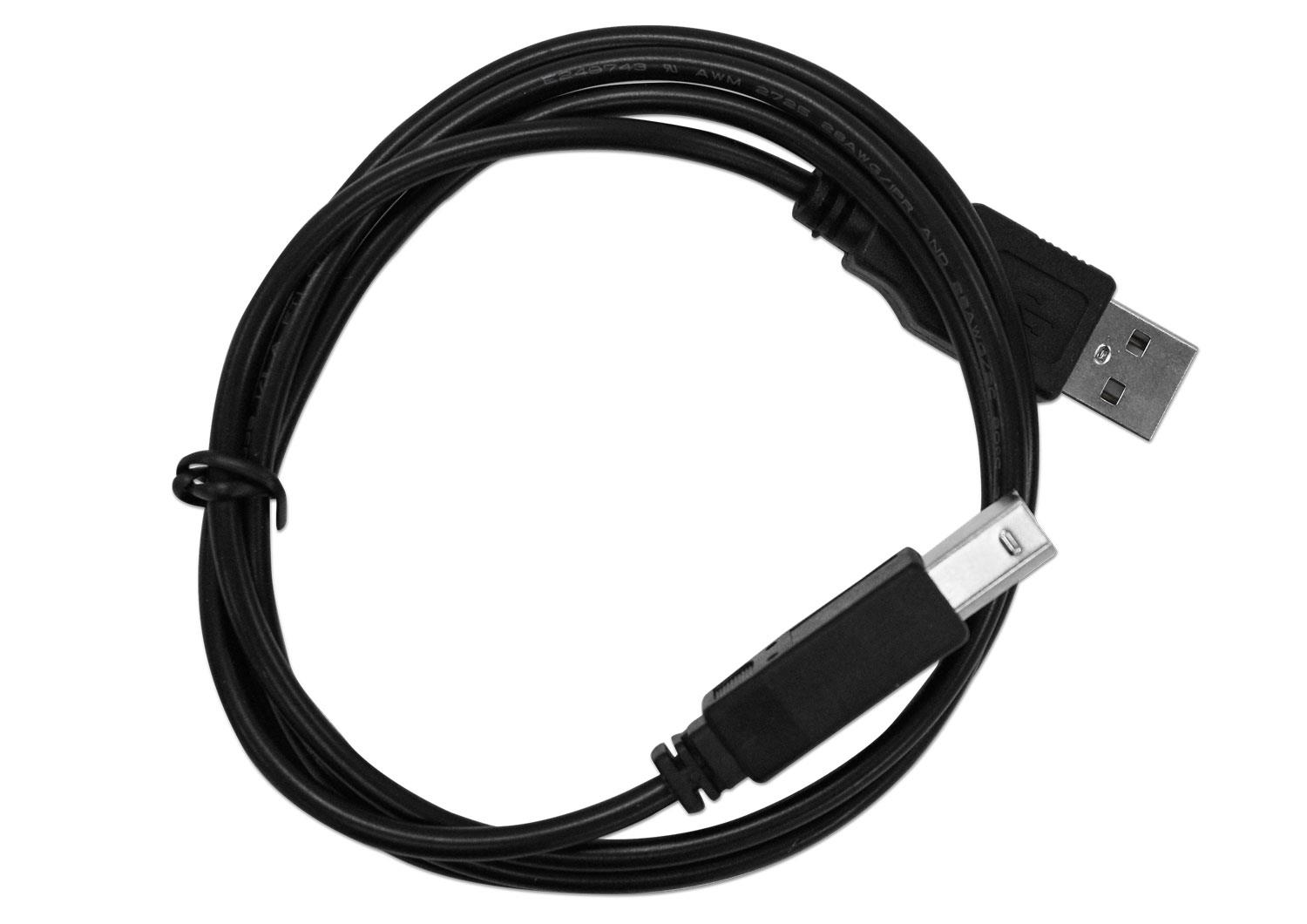
Product Images

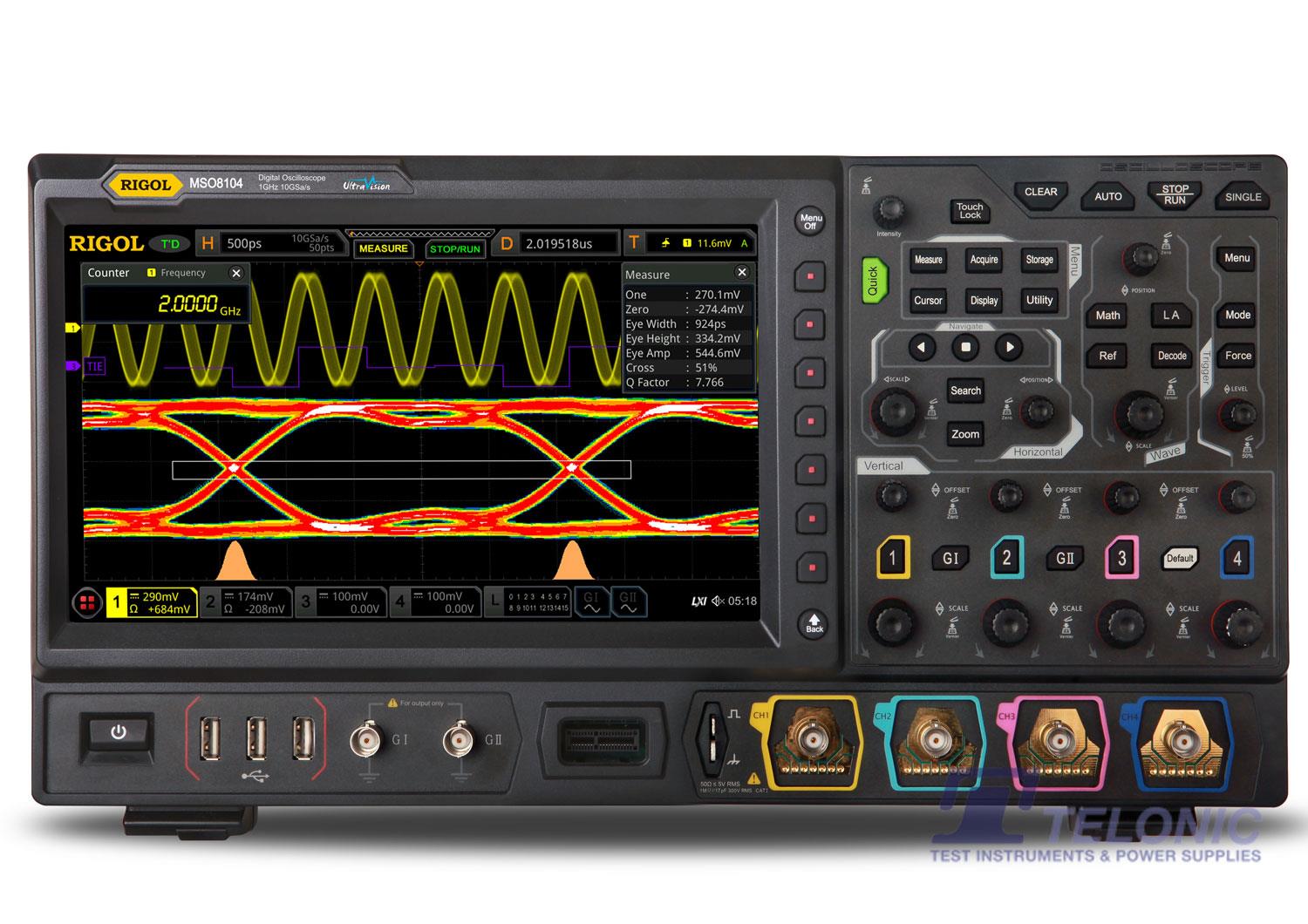
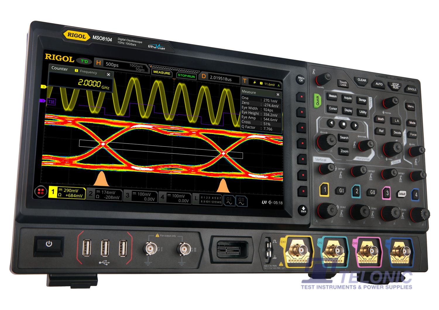
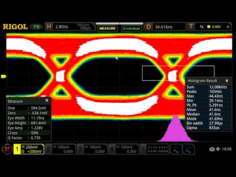
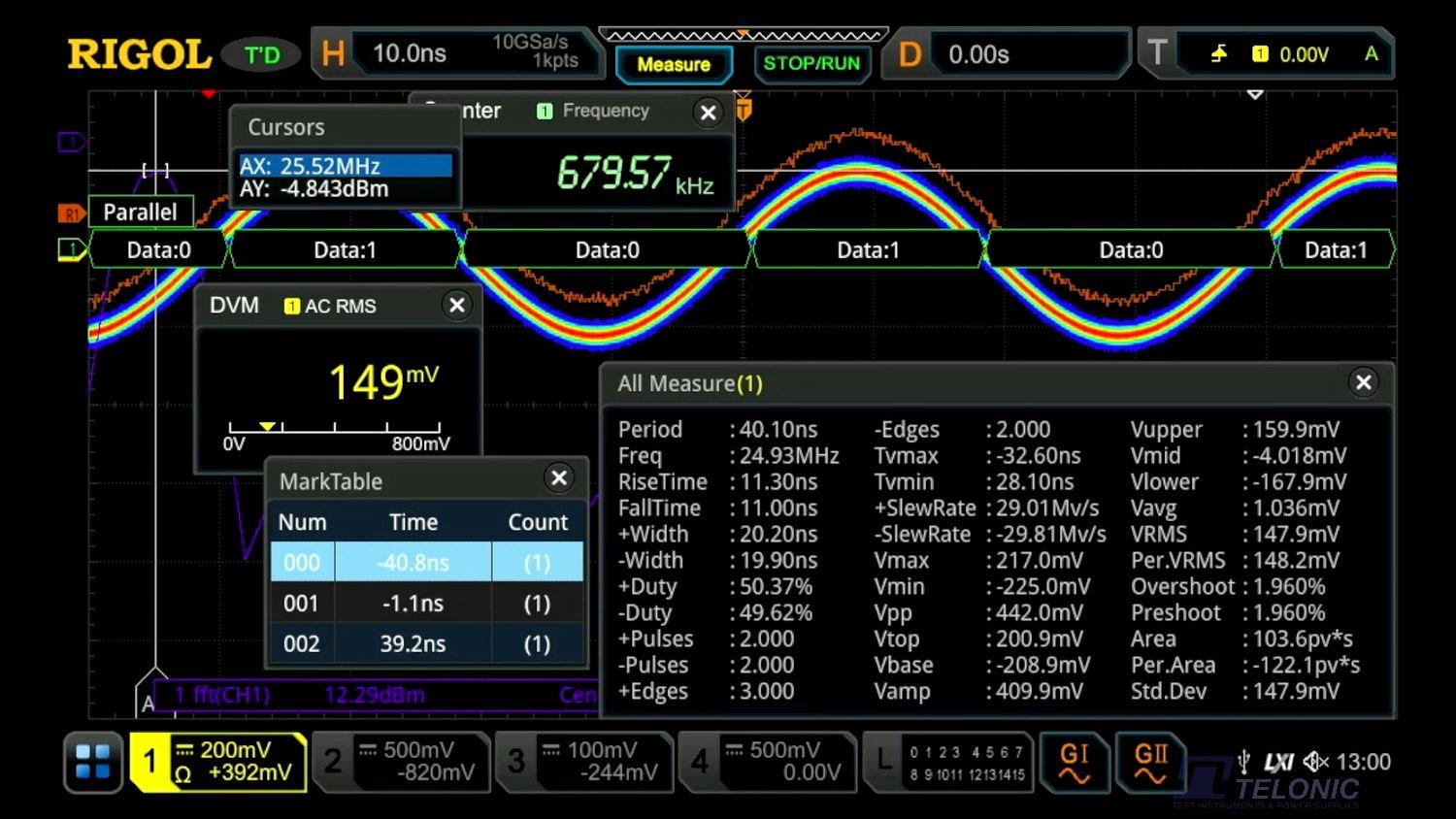
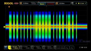
Find elusive problems in complex digital streams with long acquisitions at high sample rates

Economical and Practical Eye Diagram Pretest

2 GHz Performance for Advanced and Serial Analysis Applications

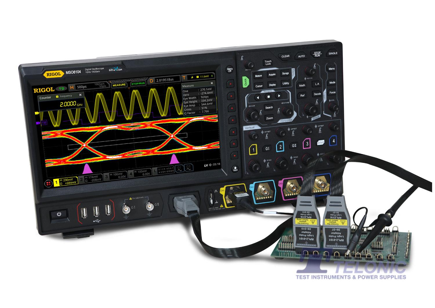
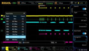
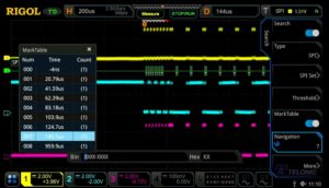
Trigger, decode, and visualise serial bus traffic to speed analysis and debug of Embedded Serial Bus designs


 Rigol MSO8000 Datasheet


Reviews
There are no reviews yet.