| Analogue Bandwidth (50 Ω, -3 dB) |
MSO8064: 600MHz
MSO8104: 1GHz
MSO8204: 2GHz |
| Analogue Bandwidth (1 MΩ, -3 dB) |
500 MHz |
Calculated Rising Time under 50 Ω
(single-channel mode, 10%-90%, typical) |
MSO8064: ≤583 ps
MSO8104: ≤350 ps
MSO8204: ≤175 ps |
| No. of Input/Output Channels |
4 input analogue channels
1 input EXT channel
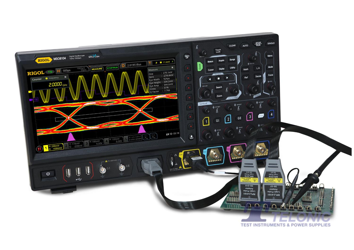
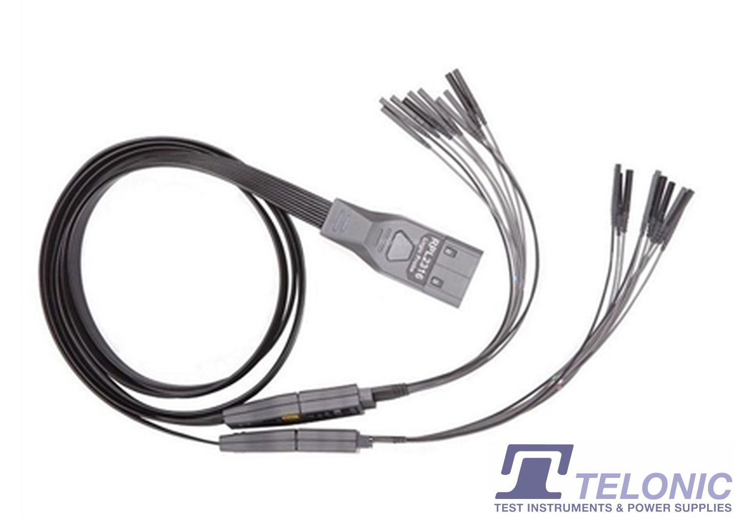
16 input digital channels (required to purchase the RPL2316 logic analyser probe)
dual-channel arbitrary waveform generator output (required to purchase the MSO8000-AWG option) |
| Sampling Mode |
real-time sampling |
| Max. Sample Rate of Analog Channel |
10 GSa/s (single-channel), 5 GSa/s (half-channel), 2.5 GSa/s (all channels)
Note: When all the channels are enabled, the sample rate is 2.5 GSa/s, and the analogue bandwidth can reach up to 1 GHz. |
| Max. Memory Depth |
analogue channel: 500 Mpts (single-channel), 250 Mpts (half-channel), 125 Mpts (all channels)
digital channel: 62.5 Mpts (all channels) |
| Max. Waveform Capture Rate |
≥600,000 wfms/s |
| Hardware real-time waveform recording and playing |
≥450,000 wfms (single-channel) |
| Peak Detection |
capture 400 ps glitches |
| LCD Size and Type |
10.1-inch capacitive multi-touch screen/gesture enabled operation |
| Display Resolution |
1024 × 600 |
| Vertical System Analogue Channel |
|
| Input Coupling |
DC or AC |
| Input Impedance |
1 MΩ ± 1%, 50 Ω ± 1% |
| Input Capacitance |
19 pF ± 3 pF |
| Probe Attenuation Coefficient |
0.0001X, 0.0002X, 0.0005X, 0.001X, 0.002X, 0.005X, 0.01X, 0.02X, 0.05X, 0.1X, 0.2X, 0.5X, 1X, 2X, 5X, 10X, 20X, 50X, 100X, 200X, 500X, 1000X, 2000X, 5000X, 10000X, 20000X, and 50000X |
| Probe Recognition |
auto-recognised RIGOL probe |
| Maximum Input Voltage |
1 MΩ CAT I 300 Vrms, 400 Vpk, Transient Overvoltage 1600 Vpk
50 Ω 5 Vrms |
| Vertical Resolution |
8 bits |
| Vertical Sensitivity Range |
1 MΩ 1 mV/div ~ 10 V/div
50 Ω 1 mV/div ~ 1 V/div |
| Offset Range |
1 MΩ: ± 1 V ( 1 mV/div ~ 50 mV/div ) ± 30 V ( 51 mV/div ~ 260 mV/div ) ± 100 V ( 265 mV/div ~ 10 V/div )
50Ω: ±1 V ( 1 mV/div ~ 100 mV/div ) ±4 V ( 102 mV/div ~ 1 V/div ) |
| Dynamic Range |
±5 div (8 bits) |
| Bandwidth Limit (Typical) |
1 MΩ: 20 MHz, 250 MHz; selectable for each channel
50 Ω: 20MHz |
| DC Gain Accuracy |
± 2% of full scale |
| DC Offset Accuracy |
≤200 mV/div (±0.1 div±2 mV±1.5% of offset value)
>200 mV/div (±0.1 div±2 mV±1.0% of offset value) |
| Channel-to-Channel Isolation |
≥ 100:1 (DC to 1 GHz), ≥ 30:1 (> 1 GHz to the rated bandwidth) |
| ESD Tolerance |
±8 kV (on input BNCs) |
| Vertical System Digital Channel |
|
| Number of Channels |
16 input channels (D0 ~ D15) (D0 ~ D7, D8 ~ D15) |
| Threshold Range |
±20.0 V, in 10 mV step |
| Threshold Accuracy |
±(100 mV + 3% of the threshold setting) |
| Threshold Selection |
TTL(1.4 V), CMOS5.0(2.5 V), CMOS3.3(1.65 V), CMOS2.5(1.25 V), CMOS1.8(0.9 V), ECL(-1.3 V), PECL(3.7 V), LVDS(1.2 V), and 0.0V
User (adjustable threshold for 8 channels in a group) |
| Max. Input Voltage |
± 40 V peak CAT I; transient overvoltage 800 Vpk |
| Max. Input Dynamic Range |
±10 V + threshold |
| Minimum Voltage Swing |
500 mVpp |
| Input Impedance |
about 101 kΩ |
| Probe Load |
≈8 pF |
| Vertical Resolution |
1 bit |
| Horizontal System Analogue Channel |
|
| Range of Time Base |
600MHz: 500 ps/div~1 ks/div
1GHz: 500 ps/div~1 ks/div
2GHz: 200 ps/div~1 ks/div
support fine adjustment |
| Time Base Resolution |
2 ps |
| Time Base Accuracy |
±1 ppm ± 2 ppm/year |
| Time Base Delay Range |
before triggering ≥1/2 screen width
after triggering 1 s to 100 div |
| Time Interval (△T) Measurement |
±(1 sample interval) ± (2 ppm×readout) ± 50 ps |
| Inter-channel Offset Correction Range |
±100 ns |
| Horizontal Mode |
YT: Default
XY: X = Channel 1, Y = Channel 2
SCAN: Time base ≥200 ms/div, available to enter or exit the SCAN mode by rotating the Horizontal SCALE knob
ROLL: Time base ≥200 ms/div, available to enter or exit the ROLL mode[5] by rotating the Horizontal SCALE knob |
| Horizontal System Digital Channel |
|
| Min. Detectable Pulse Width |
3.2ns |
| Maximum Input Frequency |
500 MHz (accurately copied as the sine wave of the maximum frequency of the logic square wave; input amplitude is the minimum swing; the shortest ground cable is required for the logic probe) |
| Inter-channel Time Delay |
1 ns (typical), 2 ns (maximum) |
| Trigger System |
|
| Trigger Source |
Analogue channel (1 ~ 4), Digital channel (D0 ~ D15), EXT TRIG, and AC Line |
| Trigger Mode |
Auto, Normal, Single |
| Trigger Coupling |
DC: DC coupling trigger
AC: AC coupling trigger
High Frequency Rejection: High frequency rejection, cut-off frequency ~ 75 kHz (internal only)
Low Frequency Rejection: Low frequency rejection, cut-off frequency ~ 75 kHz (internal only) |
| Noise Rejection |
increase delay for the trigger circuit (internal only), On/Off |
| Holdoff Range |
8 ns to 10 s |
| Trigger Bandwidth |
Internal: analogue bandwidth of the oscilloscope
External: 200 MHz |
| Trigger Sensitivity (Internal) |
1 div, <10 mV/div
0.6 div, 10 mV/div ~ 19.8 mV/div
0.4 div, 20 mV/div ~ 49.5 mV/div
0.35 div, ≥50 mV/div
When the noise rejection is enabled, the trigger sensitivity is reduced half |
| Trigger Sensitivity (External) |
200 mVpp, DC ~ 100 MHz
500 mVpp, 100 MHz ~ 200 MHz |
| Trigger Level Range |
Internal: ± 5 div from the center of the screen
External: ± 8 V
AC Line: fixed 50% |


 FREE SHIPPING £75+
 CELEBRATING 50+ YEARS
 PRICE MATCH GUARANTEE
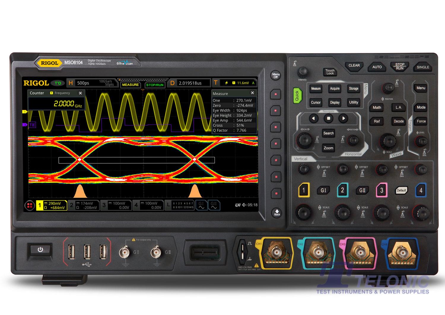


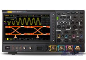
 Rigol MSO8000 Datasheet


Reviews
There are no reviews yet.