 FREE SHIPPING £75+
 CELEBRATING 50+ YEARS
 PRICE MATCH GUARANTEE


Every electrical and electronic device brought to market has to be classified and tested based on international guidelines, rules, critical values and safety conditions. Each instrument or device that passes is labelled with a special mark. In most of European countries, this will be declared by CE mark. In the US, there is an FCC approval as well as sometimes a UL listing. This identification has been established to be a standardised quality benchmark of design and manufacture. To get this certification, many tests have to be completed before a product can even be sold. One of the most common is EMC tests including interference testing and electromagnetic compatibility. Additionally, there are commonly power and environmental test requirements. Depending on the device itself, there are additional mechanical tests related to vibration or climate to be done. HALT testing (Highly Accelerated Life Test) combines vibration and temperature profile tests.
HALT is applied to the electrical and electronic components during their design phase. The devices will be stressed to achieve an accelerated aging. This is done to find possible problems that can occur during the lifetime of the product. The device will be stressed beyond the specified maximum specs (electrical and mechanical) in order to predict failure modes and future issues. Problems found based on such stress gives designers an opportunity to make improvements that can impact the long-term quality and vitality of a product before it even comes to market.
With this testing it is possible to detect possible quality issues already during the early design phase. This saves time and money, because the later in the developing phase problems are found the more expensive and time consuming the corresponding design changes. So HALT testing helps to reduce the design time and therefore reduce the time to market and also reduce the cost of the final product, so it is a very important test during the design phase of a product.
To conduct a HALT test, the device is positioned on a vibration table inside of a climate chamber. The test normally would consist of cycling of different steps, for example: cool down then heat up in a temperature change test, vibration test, or a combined stress tests. During all these test steps, the device has to be controlled and monitored with measurements stored permanently for the duration of the complete test time. Done correctly, a HALT test cycle can be an automated series of evaluations.
Temperature Measurements
Let’s look at the temperature measurement which is normally done at different locations on or around the device under test (DUT) to get a complete picture of the device’ temperature distribution during the HALT test. To be able to measure such a temperature profile within a climate chamber, you need a robust and accurate array of sensors. In this case a thermocouple is the best solution. A thermocouple is simple and robust with a broad temperature range. They are also cheap and easy to handle. The disadvantage of thermocouples is that you need a reference junction to improve accuracy. The compensation can automatically be done by an instrument like the MC3065 DMM module that is an available module for the M300 test system.
Most of the M300 switching cards include a CJC (Cold Junction Compensation) so you can measure the absolute temperature of each thermocouple. This can improve accuracy without an external reference such as ice water for comparison. There are 3 ways to provide a reference source for temperature measurements on the M300 system.
First, select a fixed reference for the highest measurement precision. This is traditionally done by putting the thermocouples in an ice bath to keep the junctions where the thermocouples meet the copper from the measurement system at a constant and known temperature. The ice bath maintains a very precise temperature as it melts to keep the liquid exactly at the melting point. Because this method can be difficult to maintain there are 2 other ways to approximate compensation for the additional junctions.
The most convenient method is to use an internal CJC. The M300 terminal blocks have an isothermal area that includes a temperature reference that can be measured by the DMM. Because the junctions between the measurement system and the thermocouple that we don’t want to measure are on the terminal block we can use the local temperature to predict offset voltage from these junctions and improve accuracy of our measurements. While not as accurate as an ice bath, this is a reliable method for correcting some measurement errors.
Lastly, the M300 system allows users to set one of the channels as an external reference. Implement this method with a more precise RTD or Thermistor that works well in your environmental range. This can provide a more accurate reading of cold junction temperatures than the internal CJC, but will be less accurate than an ice bath because there is more temperature differential across the terminal blocks that create offset.
Also the nonlinearity of the thermocouples is not a big problem because the build in multimeter takes over the calculation from voltage into temperature for all different types of thermocouples (K, J, E, etc.) Each type differs in accuracy and useful range.
Thermocouples utilise the Seebeck Effect. The Seebeck Effect is based on the physical effect that two different metals that are connected together generate a voltage related to the temperature differential of the pair of junctions of the metals. This voltage is very low, for example for a Thermocouple Type K might change 40 uVolts for every 1°C. Therefore you need a voltmeter with high resolution and accuracy like in the M300 6 ½ digit system.
For the complete test it is also necessary to be able to measure more than just the temperature. Other parameters such as voltage, current, resistance can be relevant. It is also very useful to have math functions included in the system because you can define different types of sensors to measure parameters such as pressure, movement, and more.
Rigol’s M300 Data Acquisition System
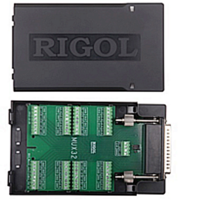
Rigol’s M300 is a complete test solution with build in capability to measure a wide range of physical and electrical parameters. Measurements of up to 256 points are possible per mainframe for temperature, voltage, current, or resistance with a common low connection, or 128 true 2 wire differential signals.
The differential modules can also be configured for automatic 4 wire resistance measurements.
Beside the measurement part, it is also possible to operate
as a control unit. With modules containing analogue and digital outputs as well as external source switching, we are able to react programmatically to process limits in order to shut down, reconfigure, or alert the engineer of a change during the automated test.
• Integrated CJC (cold junction reference) for reference temperature of Thermocouples
• Build in tables of voltage for temperature conversion
• High resolution voltage measurements down to 100nV
• Digital IO cards with up to 64lines
This is just a small selection of the build in functionality of the M300 system
There are many industrial application areas where it is absolute necessary to do these measurements described above as efficiently as possible including:
• Consumer Electronics – even including Washing Machines, Dishwasher, stovetops but also everything from phones and computers to toasters and doorbells.
• Automotive – Validation in temperature chambers of electronic parts.
• Aerospace, Transportation, Telecomm – climate/temperature overview for components, critical systems, engines, Base-Stations, etc.
• Power Plants – temperature profile of cooling towers, transformers, relays, and fuses
To make the configuration and measurement much more effective and easy to use, the M300 comes with a PC based data logging Software called UltraAcquire.
UltraAcquirePro is the extended version of the standard software tool and allows use of more than one mainframe in a single test configuration enabling extended graphing capability, data storage, and more.
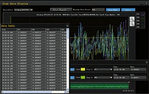
An example of a typical configuration that includes voltage measurements, resistance measurements, frequency measurements and temperature measurements with different sensor types (PT100, Thermocouple Type K, Type E, Type N) can be seen in Figure 1. With the software you can define how each sample is measured, how fast the scan should be and how quick or how accurate each measurement will be and how the data should be stored.
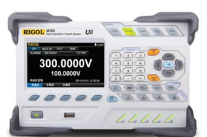
Scans can also be easily configured from the front panel as shown in Figure 2. Monitor up to 4 channels in real time on the front panel during continuous scans (as shown in Figure 3) without connecting the instrument to any software or computer. This is great for industrial or hard to reach signals where local computer control is unavailable or undesirable.
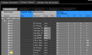
Figure 1: Configuration example using UltraAcquire software
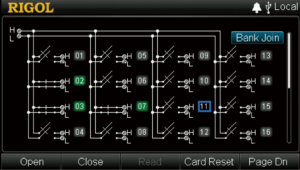
Figure 2: Switch configuration on the M300 display
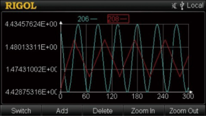
Figure 3: Channel monitoring on the M300 display
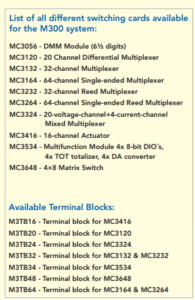
Products Mentioned In This Article: