| Bandwidth limitation |
20MHz |
| Hardware Filtering |
High pass (30KHz~ maximum bandwidth)
Low pass (maximum bandwidth ~30KHz) |
| Input coupling |
DC、AC、GND |
| Input impedances |
1MΩ±1%||15pF±3pF |
| Vertical resolution |
8 bit |
| DC gain accuracy (Amplitude accuracy) |
<±2%(1MΩ input ) |
| Vertical scale factor |
500uV/div~5V/div (1MΩ input, 500uV/div bandwidth 20MHz) |
| Channel-to-channel isolation DC to maximum bandwidth |
≥40dB(100:1) |
| Offset range |
± 2.5V (with probe multiple X1, <500mV/div), ±120V (with probe multiple X1, ≥500mV/div) |
| Noise |
≤1mV |
| Maximum input voltage |
CAT I 300V(1MΩ input) |
| Horizontal System |
|
| Time base range |
2ns/div~1ks/div |
| Time base delay range |
-14divisions to 14ks |
| Clock drift |
≤±5ppm/year |
| Time base accuracy |
±20ppm |
| Roll mode |
200ms/div~1ks/div |
| Sampling System |
|
| Sampling mode |
Real time sample rate |
Peak sampling
Sample rate 1G Sa/s |
All the sampling glitches in scanning rate are narrow to single channel 1 ns, dual channel 2 ns .four channel 4ns |
| Max duration in the max sampling rate |
1GSa/s: 28ms
500MSa/s: 56/28ms
250MSa/s: 56/28ms |
| Average |
Average of sampling for N times
N is chosen from 2, 4, 8, 16, 32, 64, 128, 256 |
| Envelope |
Envelope of sampling for N times
N is chosen from 2, 4, 8, 16, 32, 64, 128, 256, ∞ |
| Trigger System |
|
| Trigger mode |
Normal、Auto、and Single |
| Trigger coupling |
DC、AC、HF reject(>50KHz)、LF reject(<50KHz)、noise reject |
| Trigger hold off range |
200ns~10s |
| Trigger level ranges |
±10 grids from the center of the screen |
| Trigger type |
|
| Edge |
Positive, negative, or either slope on any channel input. Coupling includes DC, AC, HF reject, LF reject, and noise reject. |
| Pulse Width |
Trigger on width of positive or negative pulses that are>,<, =, ≠, or inside/outside a specified period of time (8ns~10s). |
| Logic |
Trigger when any logical pattern of channels goes false or stays true for specified period of time (8ns~10s). Any input can be used as a clock to look for the pattern on a clock edge. Pattern (AND, OR, NAND, NOR) specified for all input channels defined as High, Low, or Don’t Care |
| Nth Edge |
Trigger on the Nth rising/falling edge of the waveform |
| Runt |
By setting high and low thresholds, triggering pulses that span a level that does not cross another level captures positive and negative pulses |
| Slope |
Trigger when the waveform’s time from one level to another matches the set time condition |
| Time Out |
Starting from the intersection of the signal and the trigger level,Trigger when the trigger level is above (or below) the duration and reaches the set time |
| Video Trigger |
The triggering method for video signals is different depending on the video format. Generally, there are PAL/625, SECAM, NTSC/525, 720P, 1080I, 1080P, etc. |
| Bus |
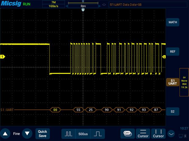
Trigger for the set bus, including UART, I2C, SPI, CAN, LIN, 1553B, 429 bus UART: start bit, stop bit, data, 0: data, 1: data, x: data, parity error
I2C: Start condition, stop condition, acknowledge loss, restart, address field no acknowledgement, frame type 1, frame type 2, EEPROM data read and write, 10-bit write frame
SPI: CS, data, X data
CAN: frame start, remote frame ID, data frame ID, remote/data frame ID, data frame ID and data, error frame, all errors, acknowledgment errors, overload frames
LIN: Synchronous rising edge, frame ID, frame ID and data
1553B: instruction/status word sync header, data word sync header, instruction/status word, remote terminal address, Manchester code error, data word, odd parity error, all errors
429: word start, word end, LABEL, SDI, DATA, SSM, LABEL+SDI, Label+Data, Label+SSM, word error, word gap error, check error, all errors, all 0 bits, all 1 bit |
| General Specifications |
|
| Power source voltage |
100~240V AC,50/60Hz |
| Power consumption |
<60W |
| Fuse |
12V DC,5A |
| Built-in Battery |
7.4V, 7500mAh |
| Temperature |
Operating: 0℃~45℃
Non-Operating: -40℃~60℃ |
| Humidity |
Operating: 5%to 85%,25℃Non-Operating: 5% to 90%,25℃ |
| Altitude |
Operating: <3000mNon-Operating: <12000m |
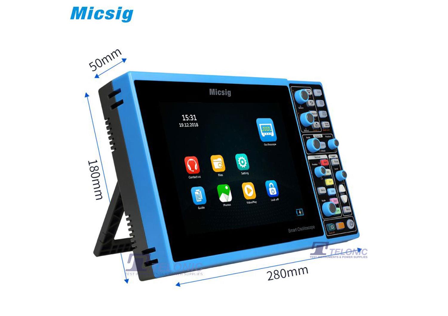
| Dimensions |
280mm*180mm*50mm |
| Weight |
2CH: 1340g, 4CH: 1425g |






 FREE SHIPPING £75+
 CELEBRATING 50+ YEARS
 PRICE MATCH GUARANTEE




Reviews
There are no reviews yet.