 FREE SHIPPING £75+
 CELEBRATING 50+ YEARS
 PRICE MATCH GUARANTEE


Description
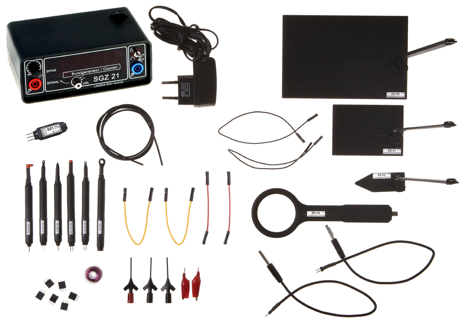
Langer EMV-Technik E1 Immunity Development System Set
The E1 is a set of EMC tools used for EMI suppression in printed circuit boards during the development phase. The developer can use the E1 set to quickly identify the causes of burst and ESD interference. This allows the developer to design suitable measures to solve the causes of the interference. It can also be used to test the effectiveness of the measures taken. The E1 test set-up is small and fits easily on a developer’s desk. The E1 set user manual describes EMC mechanisms and provides detailed descriptions of basic measuring strategies for interference suppression in printed circuit boards. The E1 set includes a generator to generate burst and ESD disturbances.
See set details below!
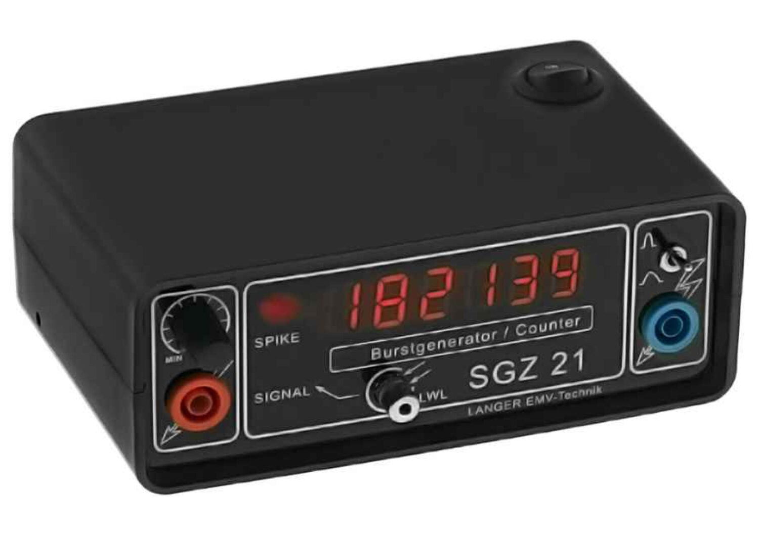 The SGZ 21 burst generator generates floating, pulse shaped disturbance. Outputs are separated symmetrically and galvanically. It can be partially coupled to constructional parts, cables, shielings, ground connections; directly in assemblies or via field sources of a device under test. A pulse rate counter with an optical input which detects signals from assemblies is integrated into SGZ 21.
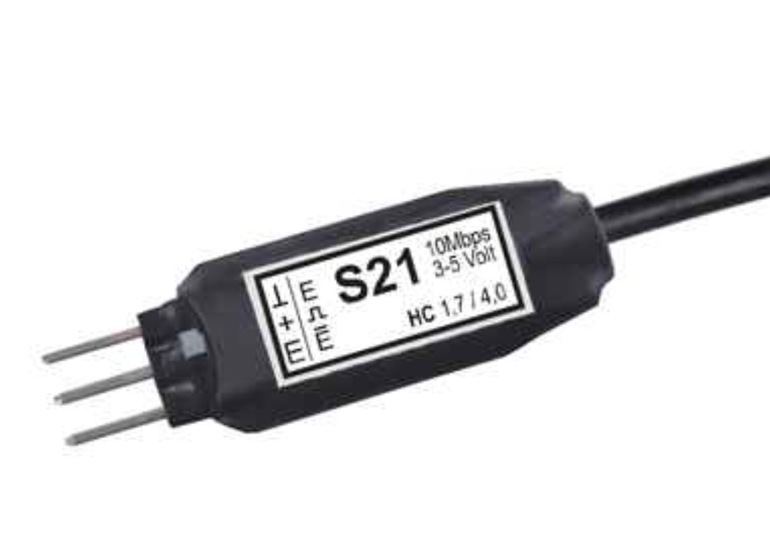 The S21 sensor is a digital probe for nonreactive transmissions of binary signals out of the device under test during a burst or ESD testing. The sensor is positioned directly onto the PC board of the device under test and is powered by the device under test. In the sensor the digital signal is transformed into an optical signal and is transmitted via a fibre optical cable to the receiver/oscilloscope.
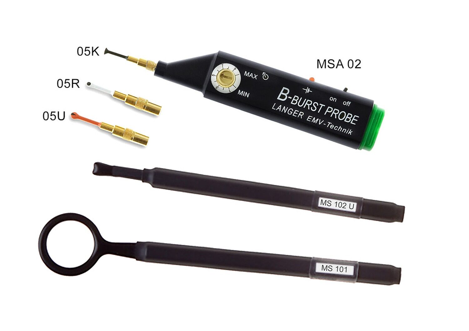
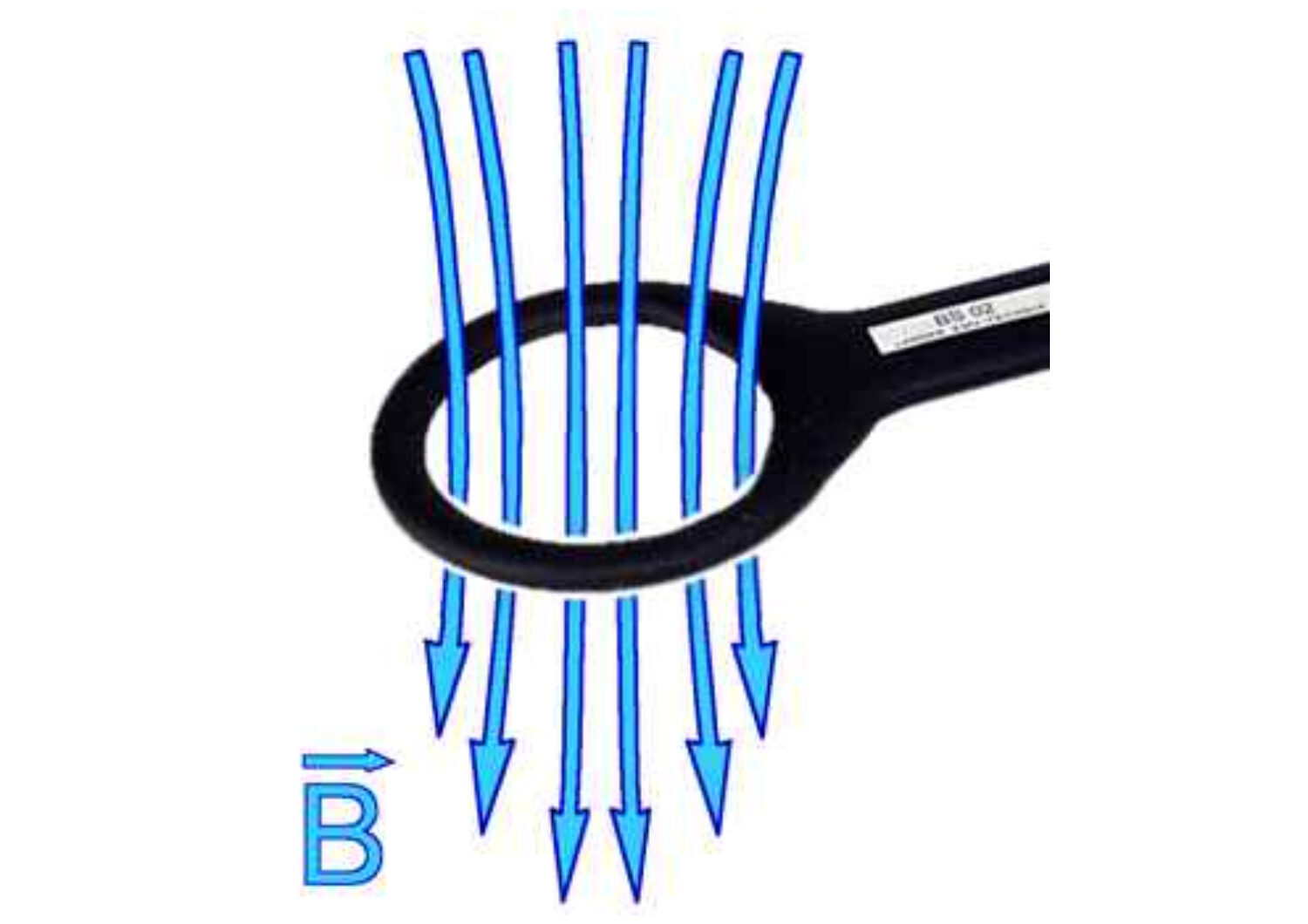 The BS 02 magnetic field source is designed for localizing weak spots in the layout. It generates a B field bundle of > 5 cm in diameter and is suitable for extensive pulsing of housing surfaces and internal areas, connection technology and assemblies with conducting path structures and ICs. It detects magnetic sensitive weak spots.
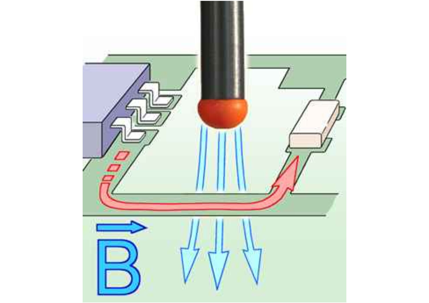 The BS 04DB generates a B field bundle in millimetre range and is specially designed to localize critical parts of conducting paths, components and component connectors. The field which emits from the field soures head is guided above the device under test.
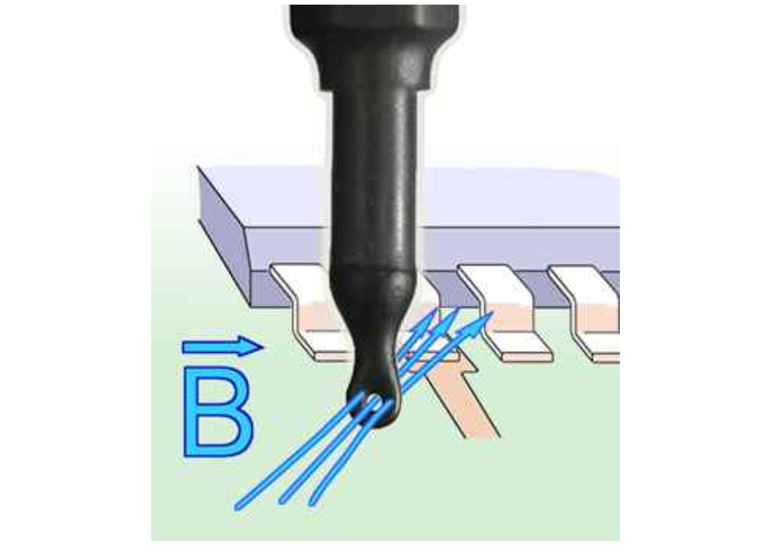 The BS 05D generates a B field with a diameter >3mm. The field lines run at 90° to the field source. The field source is suitable for localizing weak spots between two printed circuit boards and in hard to reach spots of assemblies. Before using the BS 05D, the weak spot should be roughly localized with the BS 02 or BS 04BD field source.
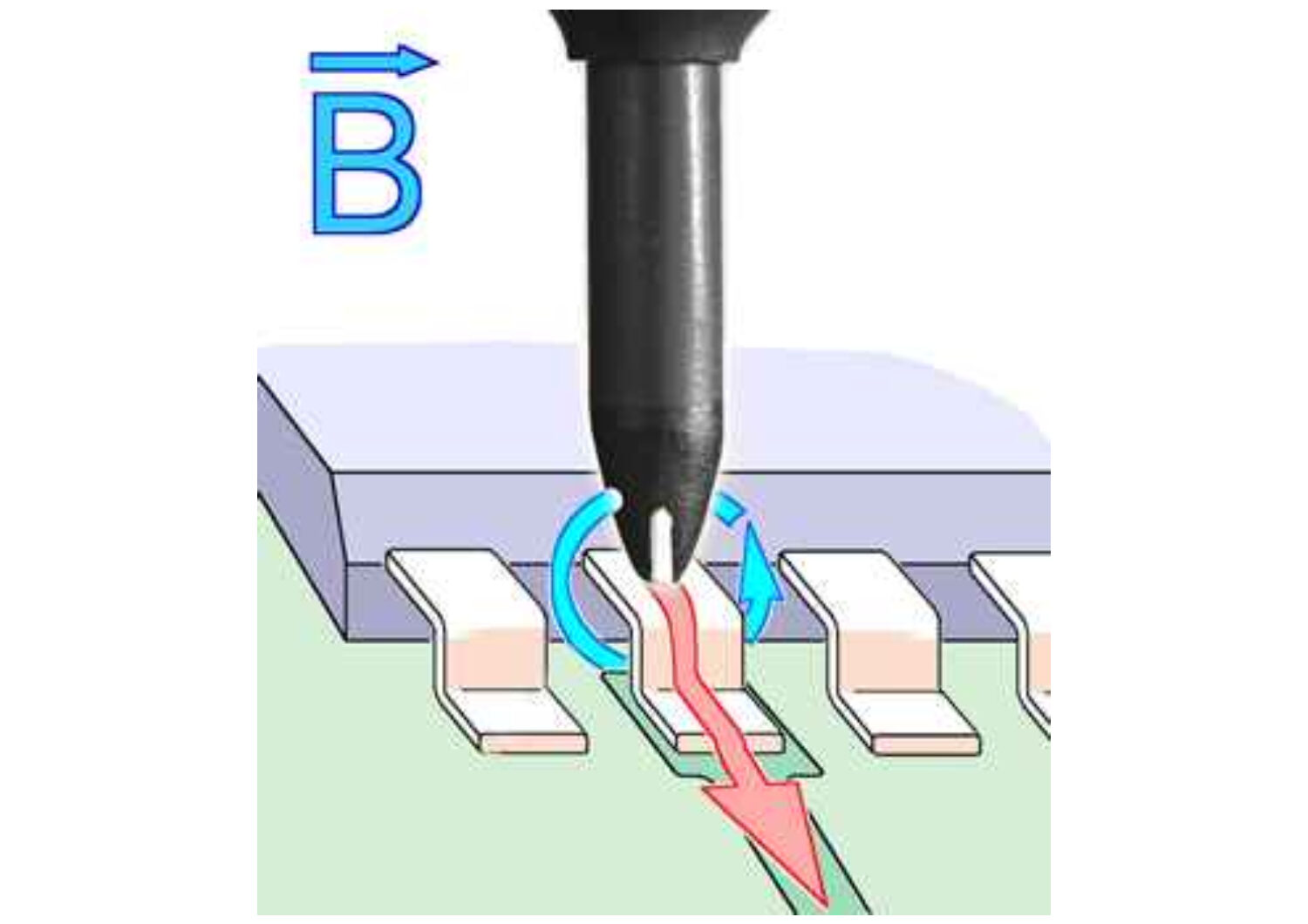 The BS 05DU generates a magnetic field in millimetre range. It functions like a coupling clamp and is used for selective coupling of disturbance current in single conducting paths, IC pins, SMD components and thin cables (flat ribbon cables).
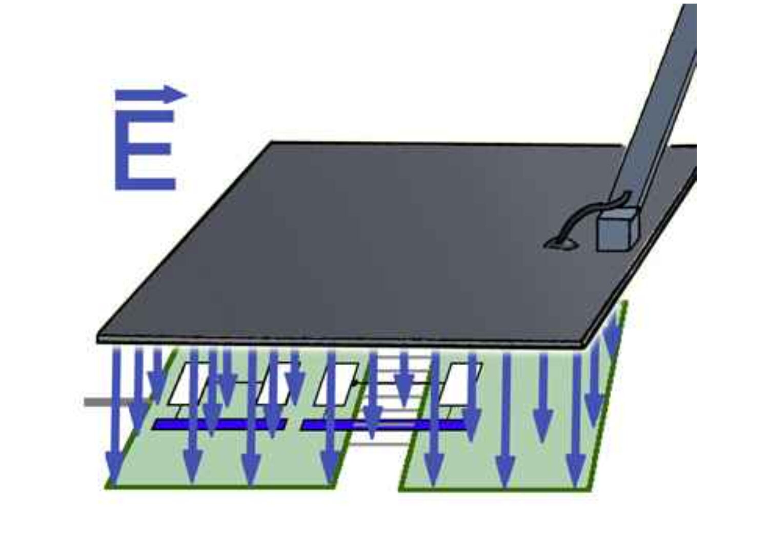 ES 00 allows electric couplings, which are either large (150 cm²) or with the edge of the field source head also linear. E field sensitive weak spots often range extensively over 10 to 15 cm (LCD display; bus systems). Large field sources like ES 00 detect such weak spots. ES 00 can also be used for coupling disturbance current into assemblies.
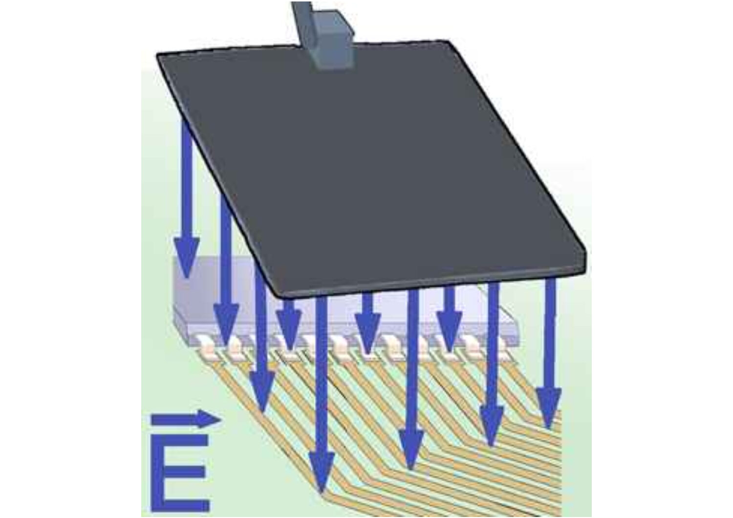 The field source is suitable for pulsing planar or line shaped weak points in the range from 5 to 10 cm. It ranges between the field source ES 02 and ES 00. ES 01 can also be used for coupling disturbance current into assemblies.
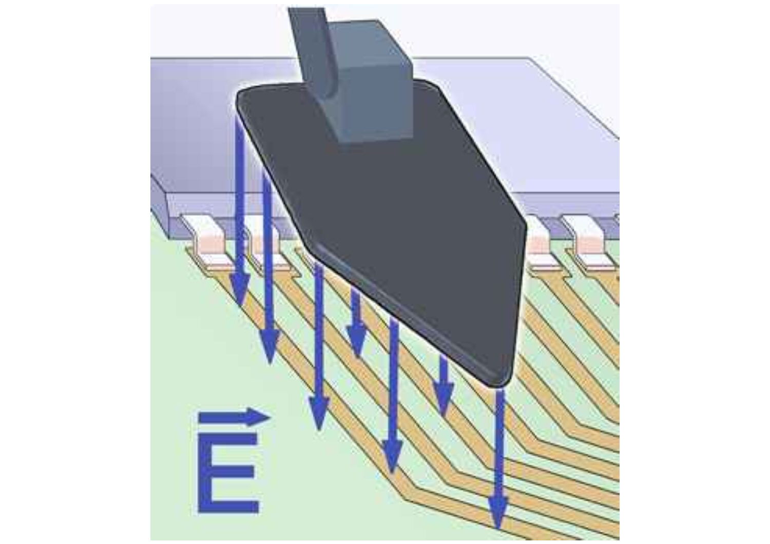 The surface of the E field source head allows the extensive coupling into housing surfaces and interior areas, connection technology and assemblies with conducting path structures and ICs. The tip can be used for the localization of small E- field sensitive weak spots (conducting paths, quartz crystal, pull-up resistance, ICs).
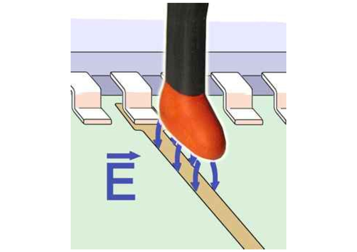 The E field source has a small line shaped coupling electrode in its field source head. Therefore it is suitable for positioning on conducting paths, small components and their connectors, wires and singe SMD components like resistors and capacitors. Single male contacts or cores of flat ribbon cables can be tested.
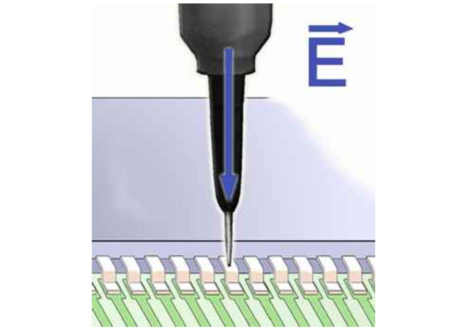 The ES 08D E field source is a probe tip, which is used to determine the sensibility of an IC pin or a conductor. During the test the probe tip is bonded with the pin / conducting path. By changing the intenstity of the burst impulse at SGZ 21 the sensitivity of the pin is determined.
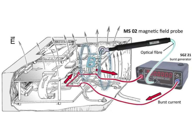
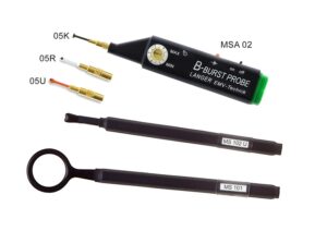
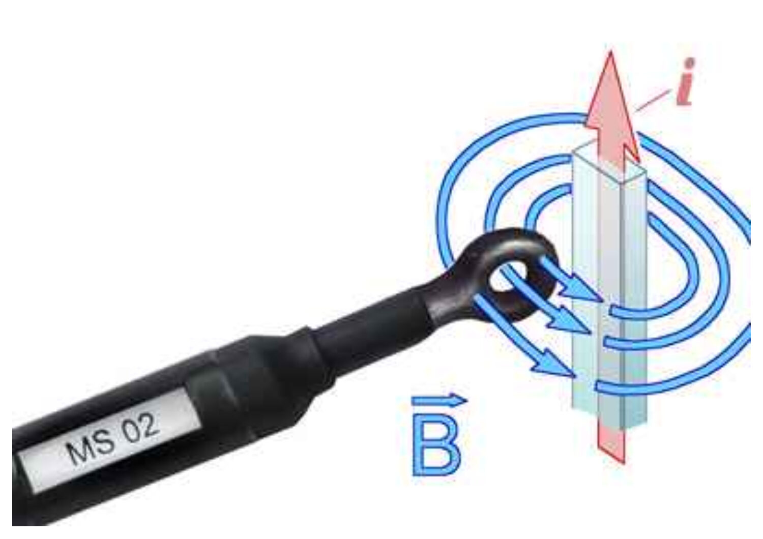 The magnetic field probe is designed for measuring bust magnetic fields within the device under test. The paths of the disturbance current can be detected. The MS 02 magnetic field probe is used together with SGZ 21.
Product Images
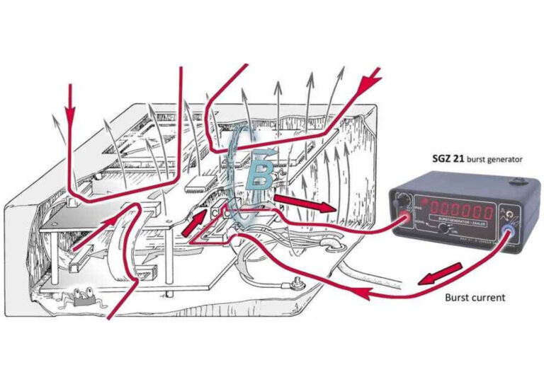
Analysis of disturbance current paths
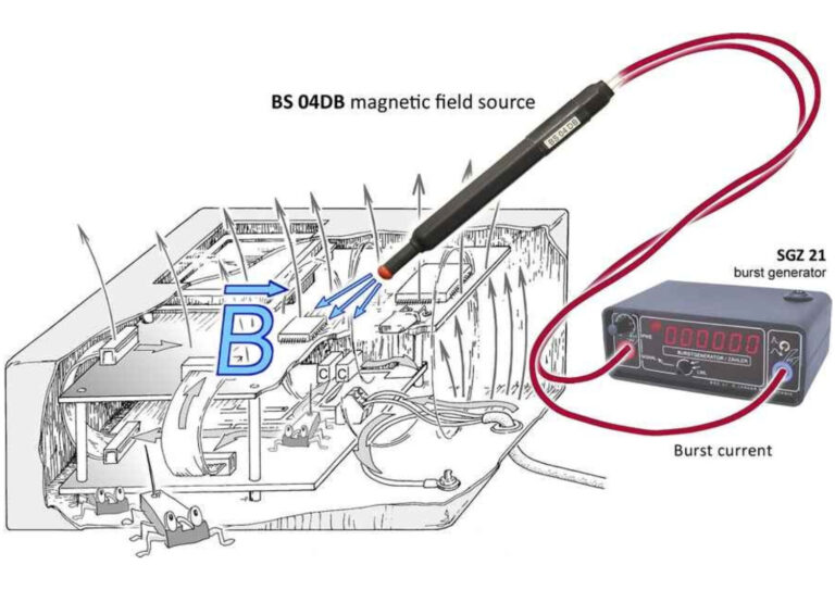
Fault localization with field sources
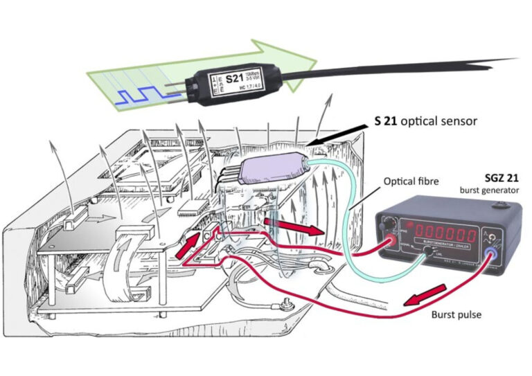
Monitoring of EUT logic signals

 BS-02 Magnetic Field Source

Reviews
There are no reviews yet.