 FREE SHIPPING £75+
 CELEBRATING 50+ YEARS
 PRICE MATCH GUARANTEE


EMC Precompliance Testing: Immunity/Susceptibility
Solution: Products that contain electronics can be sensitive to radio frequency (RF) interference. Devices that experience RF interference can be prone to improper or failed operations. Products that suffer problems when exposed to RF interference are said to be susceptible to interference while products that do not exhibit issues when exposed to RF interference are said to be immune to interference.
RF interference can cause:
- Scrambled display information
- Slow, Frozen, or locked operations (no response from keys, knobs)
- False or noisy data
- System reset or reboot
Design analysis, including part selection, shielding, and cable selection is the first step in creating a product that is capable of operating “as expected” under a certain degree of RF interference, but testing early under real world conditions is one sure way to determine if your design is susceptible to any issues with RF.
In this application note, we are going to show you how an RF generator and some simple tools can help you identify weaknesses in your product design.
A Word about Precompliance
Most governments have regulations in place that specify the amount of electromagnetic interference (EMI) a product can emit into the environment (radiated emissions) and conduct down the power cord (conducted emissions).There is also an increasing number of regulations that cover how much EMI a product can endure from outside sources (susceptibility).
Products being sold within the areas covered by these regulations must comply with the defined test limits. Compliance tests use these regulations to define the proper instrumentation, physical setup, and experimental techniques and experience to correctly record and report properly. This testing is very important and required for legal sale of the product within the covered area. Unfortunately, compliance testing can be expensive and difficult to execute due to the specialised equipment and knowledge required to properly conduct the tests.
Precompliance testing simulates the major details of a compliant test setup at a lower investment in time and money. Before you go to a compliance lab for testing, you can use precompliance tests to gather information about the performance of a design, make changes (if needed), and retest.. all in an effort to minimise the return trips to the compliance lab.
A word of caution, however. Precompliance data can be useful in hunting down many, if not all, of the non-compliant areas of a design but it is not a substitute for testing at a fully accredited compliance lab. Ultimately, the company (you) is responsible for proof of compliance to the full regulations for your product.
Radiated Susceptibility
Radiated susceptibility tests involve observing the operation of a device-under-test (DUT) while it is being subjected to a known RF source. The signal is delivered to the DUT using antennas for far-field testing or near field probes for board level tests.
Most radiated susceptibility regulations are based on IEC 61000-4-3 which defines the test signals range from 80-1,000MHz. This signal can be modulated by a 1kHz AM sine wave with 80% modulation depth. The modulated signal helps to quickly identify any rectification issues within sensitive circuit elements.
In far-field tests, an RF signal source, like the Rigol DSG3000 or DSG800 series is connected to an antenna that is set up a meter or two from the DUT. The RF source is then configured to source an output with 80% AM modulation at 1kHz. The amplitude should be set as high as possible, and the carrier frequency can be set at 9kHz.
NOTE: The DUT should be configured in its most commonly used state. All cabling (power, I/O, etc..) should be connected and in place. Cables can act like antennas and can directly influence performance.
Observe the DUT for any functional changes or issues such as a glitching or noisy display. Now, increase the carrier frequency and check the DUT. Step the center frequency of the generator and continue to observe the DUT, making note of the carrier frequencies that cause issues and the type of problems observed. After you have completed stepping up to 1GHz, you can rotate the DUT with respect to the antenna and re-test if you desire a more thorough test.
NOTE: Antennas and should only be used in shielded anechoic or semi- anechoic chambers to prevent interference with communications and emergency broadcast bands. It is illegal to broadcast over many frequency bands without proper licensing.
The use of an RF source like the Rigol DSG3000 (DSG3000B) or DSG800 series allows you to the flexibility to adjust the wavelength, power, and modulation of the output to help identify problem areas quickly.
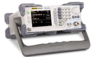
Figure 1: The Rigol DSG800 and DSG3000 RF Source.
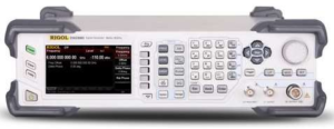
Figure 1: The Rigol DSG800 and DSG3000 RF Source.
Near Field testing is helpful because it does not require specialised chambers for testing. The E and H field probes only produce strong fields at distances less than 1” from the tip of the probe and do no radiate efficiently enough to cause problems with broadcast and emergency systems. Their small size also allows you to pinpoint the RF at specific circuit elements.
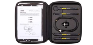
Figure 2: RIGOL’s NFP-3 set of Near Field Probes. These are all H field probes.
The RF source is configured exactly as in the far-field test, but this time, the probe tip is placed very close to the circuit or elements of the board at each carrier frequency. As you scan across the circuit, observe the DUT and be sure to check for any issues. Especially near sensitive analogue circuitry.
In the figure below, we removed the shielding from an oscilloscope board and used a probe and DSG3000 to deliver RF signals into the sensitive analogue front end. As you can see, with the shielding removed, the RF causes data corruption and changes the waveform significantly.
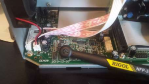
Figure 3: Using a near field probe on an unshielded Oscilloscope analogue input circuit.

Figure 4: Oscilloscope data with shielding in place.
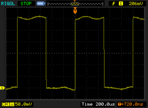
Figure 5: Oscilloscope data without shielding.
Additional testing
Another useful test technique is to use a current probe and RF source to deliver RF signals to cables connected to the DUT. Cables can act like antennas and couple undesired signals to the DUT. You can use this setup to step through different frequencies and check the susceptibility of your design. Commercial current probes can be used.. but an acceptable current probe can be built using a snap-on ferrite choke, a few winds of insulated wire, some epoxy, and a BNC connector as shown below:
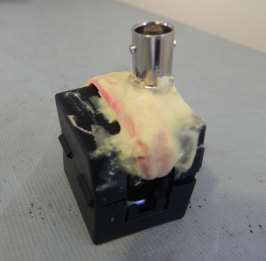
Figure 6: Homemade current probe.
Simply setup your DUT and connect all of the cables that are common to its usage. Configure the source to output maximum power with the same 80% 1kHz AM modulation that was suggested for far and near field tests earlier and observe the DUT for problems. Step the carrier frequency and observe. Perform this test to the maximum desired frequency and repeat the process on each cable used with the DUT.
NOTE: Clamp probes should only be used in shielded anechoic or semi- anechoic chambers to prevent interference with communications and emergency broadcast bands. It is illegal to broadcast over many frequency bands without proper licensing.
To demonstrate the use of a current probe, we performed an experiment on a USB powered demonstration board. We used a DSG3000 and a homemade probe clamped to a non-filtered USB cable connected to the board and we monitored the output signal.
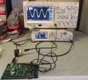
Figure 7: Injection of RF to an unfiltered USB cable.
With no RF applied, the data was smooth.
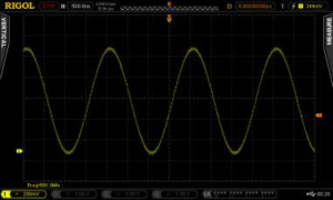
Figure 8: Sine wave from board without RF interference.
But, when an RF signal was applied, the output began to show signs of interference. The worst interference occurred at a carrier of 110MHz, as shown below.
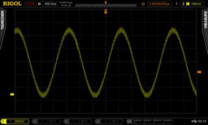
Figure 9: Noisy data showing RF interference at 111.1MHz due to injected noise.
In conclusion, an RF source like the Rigol DSG3000 or DSG800 and some simple tools can enable you to test your designs for immunity issues early in the development process. Saving your company time and money.
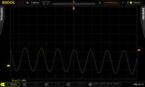
Figure 10: Zoomed data to show details.
Products Mentioned In This Article: