Noise is an unwanted but inevitable problem in test systems including power supply sources, except batteries, which are low-noise power sources. Some amount of noise is always generated or relayed by power supplies; however, a power supply is a device that supplies power to another device, and not intended to be used by itself. Power supply noise should be low enough so as not to interfere with the neighbouring equipment or test results.
This white paper will discuss how to mitigate the power supply noise in the test systems, showing two test system examples – a DC/DC converter test system and an RF amplifier test system. It particularly explains how to setup the power supply or measurement equipment in the test system, including the wiring method.
1. Power Supply Noise in DC/DC Converter Test Systems
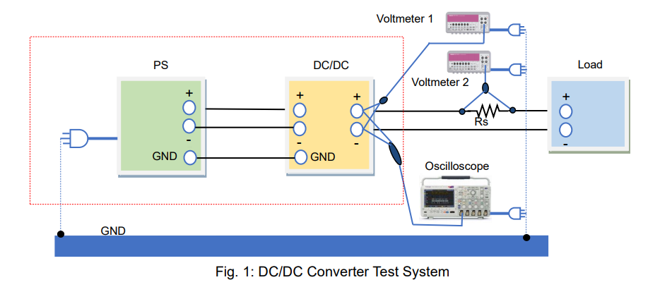
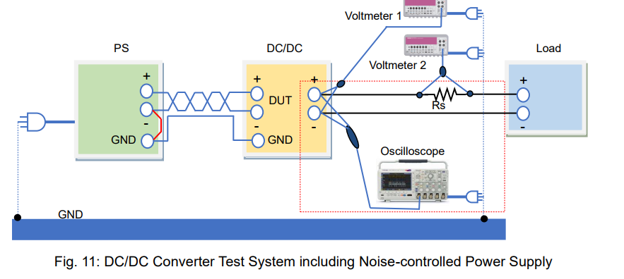
Figure 1 shows the test system. The DUT is a DC/DC converter powered by a power supply with a load resistor connected. An oscilloscope measures the output voltage ripple of the DC/DC converter; voltmeter 1 measures the output voltage; the output current can be taken by measuring the voltage across the shunt resistor from voltmeter 2. The input source of the power supply, oscilloscope, voltmeter 1 and 2 are grounded to the GND for safety.
1-1. What is Power Supply Noise?
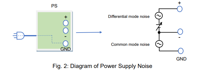
Power supply noise can be divided into two types: “common mode noise” generated in a ground loop and “differential (normal) mode noise” appearing in the positive and negative lines. The common mode noise is applied on the ground (GND) line and negative line. The GND terminal is grounded when the power cable is plugged into an outlet.
1-2. How to Minimise Power Supply Noise
This section explains how differential mode noise and common mode noise enter a system and how these noises can be reduced.
1) How Differential (Normal) Mode Noise Enters DUTs
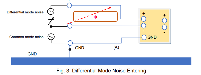
The positive and negative cable wiring deliver the differential mode noise to your DUT. How the DUTs reject the noise depends on their power supply rejection ratios (PSRR). The DUT’s tolerance against the differential mode noise can be measured by determining how the noise frequency characteristics affect the outputs of DUTs. For reducing noise, using cable inductance and placing a capacitor with good high-frequency characteristics at the input of your DUT may help. With a wire loop, magnetic flux may be generated due to the differential mode current as shown in figure 3. This noise is emitted into the air, affecting the neighbouring equipment. To suppress this noise emission, twist the positive and negative cables.
2) How Common Mode Noise Enters DUTs
Common mode noise appears in the positive and negative lines of the power supply carried through the GND contact (common ground). That is to say, common mode noise enters both the GND and negative line. The same amount of common mode noise (voltage) also appears in the positive line, where the differential mode noise (voltage) and DC voltage are applied.
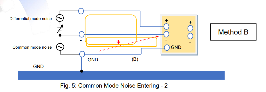
When the common mode noise enters the DUT, it may be converted to the differential mode noise depending on the stray capacitance between the signal line and GND line of the DUT, and this can affect the output performance of the DUT. If there is a large ground loop and wire loop, a magnetic flux may be generated due to the noise current as shown in figure 4, and this noise is emitted into the air, affecting the neighbouring equipment (e.g. measuring devices). To reduce this noise, make the loop smaller. It can be done by grounding the DUT’s GND by following method ‘B’ in figure 5.

3) Good Defense for Common Mode Noise
In both cases shown in figure 4 and 5 (method ‘A’ and ‘B’), the ground loop is present, so common mode noise and magnetic flux are unavoidable. To prevent common mode noise emission, add a capacitor or short wire between the GND and negative terminals of the power supply as shown in figure 6.

4) Poor Defense for Common Mode Noise
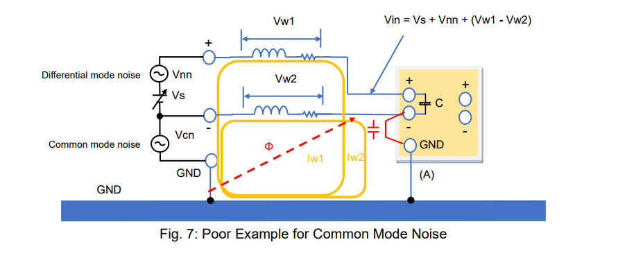
Figure 7 shows an example similar to figure 6: a capacitor or short wire is added between the GND and negative terminals at the input of the DUT. It appears good, but noise currents Iw1 and Iw2 increase, and the magnetic flux becomes stronger than those of figure 4 and figure 5. This causes an electric wave, which can interfere with measuring systems and other neighbouring equipment. It also assists the generation of the differential mode noise (Vw1 – Vw2) due to the difference of the wire impedance.
5) Common Mode Choke Coil
In the case of figure 7, if the noise current reduces, the magnetic flux noise can also decrease. In figure 8, after adding a common mode choke coil, the cable impedance on the wire loop will increase. Accordingly, Iw1 and Iw2 will reduce. The common mode choke coil can also block external noise (magnetic flux) so that it can be added in the system example shown in figure 6. Figure 9 shows the relationship between the impedance of the common mode choke coil (Z) and Iw. If Z increases, Iw decreases. As a result, the magnetic flux will decrease.

6) Power Supply Noise-Reduction Technique
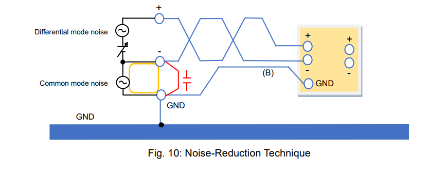
Now, let’s summarise how to control the power supply noise. Figure 10 shows one example of a reduced-noise test system. If the noise persists on your test system, try the following:
A) Twist the output cables of the power supply. *1
B) Connect the output terminal of the power supply to the GND or connect them with a capacitor.
C) Avoid the ground loop.
*1: It is also effective to apply a common mode choke coil to the power supply output.
1-3. Power Supply Noise in Measurement Equipment
Figure 11 shows the noise-controlled test system. The DUT is a DC/DC converter. However, even with such system, the power supply noise cannot be fully suppressed. Furthermore, the DC/DC converter inevitably generates noise as well. The DC/DC converter noise can be also classified as differential mode noise and common mode noise.
The test instruments have notable characteristics. The voltmeters are isolated from the power supply’s GND, but the oscilloscope’s GND is connected to it.
This section explains how the common mode noise affects oscilloscope measurements and how to handle it.
1) How Common Mode Noise Affects Oscilloscope Measurements
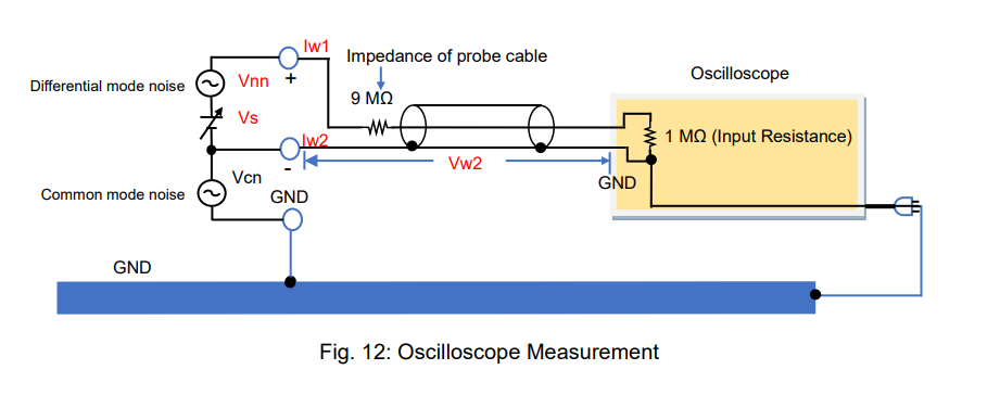
Figure 12 shows that the DC/DC converter is measured with the oscilloscope at its input terminal. In the ground loop, the common mode noise voltage (Vcn) appears, and the noise current (Iw2) circulates through the outer conductor of the probe cable. Then noise voltage (Vw2) is generated between the negative terminal of the DC/DC converter and the oscilloscope’s GND. Consequently, the voltage measurement is calculated as Vs + Vnn + Vw2. It is affected by the common mode noise.
The input impedance of the oscilloscope probe is 10 MΩ as shown below, so Iw1 caused by Vcn cannot flow through the center conductor of the probe cable. Accordingly, no noise voltage generates due to Iw1. Only Vw2 is included in the measurements.

2. Power Supply Noise in RF Amplifier Test Systems
Figure 14 shows a noise-controlled test system. The DUT is an RF amplifier. The RF signal from the RF signal generator is amplified by the RF amplifier. The output of the RF amplifier is measured by a spectrum analyser. RF amplifiers are small signal-tuned amplifiers that amplify small signals at radio frequencies. The chassis of RF amplifiers is at GND potential. Therefore, an external magnetic flux caused by the common mode noise should be removed from RF amplifier measurements.
The magnetic flux can be generated around the output of the power supply as well as from the chassis or power supply line.
This section explains how the external magnetic flux affects the RF amplifier measurements and how to handle the noise.

1) Why External Magnetic Flux Affects RF Signals
Figure 15 shows that the RF signal generator output connector is connected to the RF amplifier input port by a coaxial cable. In this system, the ground loop is obviously formed, so if an external magnetic flux caused by common mode noise passes through this loop, the noise current (Iw) flows through the outer conductor of the coaxial cable. Thus, this generates the noise voltage (Vw). Vw is added to the RFSG output through the input port of the RF amplifier. The RF coaxial cable has an impedance of 100 Ω in total at its center conductor. As an external magnetic flux passes this loop, the current does not flow through the center conductor with high impedance, so that the noise current (Iw) only flows through the outer conductor of the coaxial cable. These unbalanced currents lead to adding Vw to the RF signals.

2) How to Minimise Common Mode Noise
The above noise issue is caused by the ground loop. To solve it, break the ground loop by placing an isolation transformer as shown in figure 16 (see also Sec. 1-3-2 above).

Another solution is to wind the coaxial cable on a toroidal core, which blocks the current from flowing through the outer conductor of the coaxial cable.
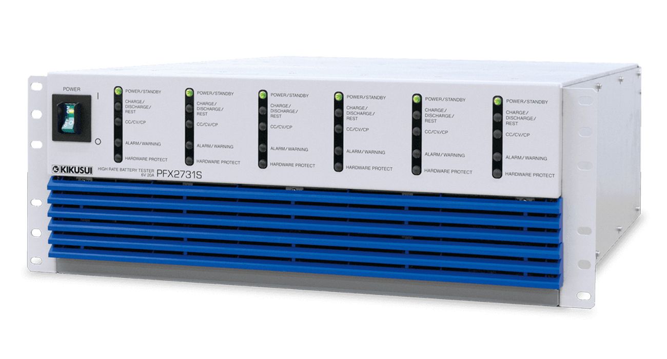
Products Mentioned In This Article:
Full range of Kikusui products please see HERE






 FREE SHIPPING £75+
 CELEBRATING 50+ YEARS
 PRICE MATCH GUARANTEE


