 FREE SHIPPING £75+
 CELEBRATING 50+ YEARS
 PRICE MATCH GUARANTEE


This part covers the measurement workflow for commercial, industrial and medical products: selecting a suitable site, recording ambient signals, configuring the antenna and analyser chain, and applying the corrections needed to express the result as field strength.
Control the site and ambient environment
Survey the site with the DUT switched off before relying on any result. Broadcast, mobile and nearby electronic equipment can mask DUT harmonics or create peaks that appear to belong to the product. A quieter location, controlled room or shielded environment improves repeatability, but the ambient trace should still be retained.
Keep the antenna-to-DUT distance, antenna height, polarisation, product orientation and nearby objects consistent. If the setup changes, treat the next trace as a new measurement rather than a direct before-and-after comparison.
Build and document the signal chain
- Calibrated antenna with antenna factor versus frequency.
- Low-loss coaxial cable with known frequency-dependent loss.
- Preamplifier gain or attenuator loss where used.
- Spectrum analyser or EMI receiver configured for the required band, bandwidth and detector.
Use one documented sign convention for corrections. A common expression is: field strength in dBµV/m = analyser reading in dBµV + antenna factor in dB/m + cable and attenuator losses in dB – preamplifier gain in dB.
Configure the analyser
- Use peak detection for a fast initial scan, then confirm critical frequencies with the detector required by the applicable standard.
- Set the resolution bandwidth and video bandwidth for the test band rather than relying on the power-on default.
- Use smaller spans or segmented sweeps when the number of measurement points is insufficient for the required frequency spacing.
- Apply attenuation or preselection if strong ambient signals risk overloading the front end.
- Allow enough dwell or sweep time to capture intermittent or broadband emissions.
Measurement sequence
- Save a DUT-off ambient trace.
- Operate the DUT in the mode expected to create the highest emissions.
- Scan both antenna polarisations and repeat permitted DUT or antenna rotations to find the maximum.
- Apply the frequency-dependent correction data.
- Overlay the appropriate limit and record the margin at critical frequencies.
- Repeat the measurement after each design change without altering the controlled geometry.
Troubleshooting poor correlation
- Check whether antenna factor, cable loss or preamplifier gain has been omitted or applied with the wrong sign.
- Increase analyser attenuation to see whether suspicious peaks are internally generated.
- Repeat the ambient scan at a different time if external signals have changed.
- Check that the DUT mode, cable routing and auxiliary equipment match the earlier setup.
- Use a near-field or current probe to determine whether the dominant path is enclosure radiation or common-mode cable current.
-
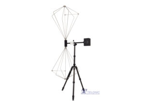
Tekbox TBMA2 Biconical Antenna 30MHz to 300MHz
£933.00 (£1,119.60 inc. VAT)2 in stock (can be backordered)
Availability: Stock models delivered next working day (UK only) for orders placed before 16:30 (Mon - Fri)
Add to basket
-
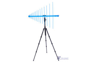
Tekbox TBMA3 250MHz to 1.3GHz LOG Periodic Measurement Antenna
£1,167.00 (£1,400.40 inc. VAT)2 in stock (can be backordered)
Availability: Stock models delivered next working day (UK only) for orders placed before 16:30 (Mon - Fri)
Add to basket
-
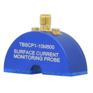
TEKBOX TBSCP1-10M500 9 kHz to 600 MHz RF Current Monitoring Probe
£480.00 (£576.00 inc. VAT)Available on back-order
Availability: Stock models delivered next working day (UK only) for orders placed before 16:30 (Mon - Fri)
Add to basket
-
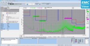
TEKBOX EMCview Pro PC Software Licence
£653.00 (£783.60 inc. VAT)Available on back-order
Availability: Stock models delivered next working day (UK only) for orders placed before 16:30 (Mon - Fri)
Add to basket