 FREE SHIPPING £75+
 CELEBRATING 50+ YEARS
 PRICE MATCH GUARANTEE


Military and automotive radiated-emissions tests use the same measurement principles as commercial pre-compliance work, but the prescribed geometry, frequency bands, antennas, harness arrangements, bandwidths and detectors can be different. Always work from the applicable edition of the controlling standard and the agreed test plan.
This page is a pre-compliance workflow guide. It does not replace MIL-STD-461, CISPR 25, an OEM specification or advice from the accredited laboratory responsible for the formal test.
MIL-STD-461 radiated-emissions preparation
Requirements such as RE102 define frequency-dependent equipment and setup details. Low-frequency work may use a loop antenna, while higher bands can require biconical, log-periodic or horn antennas. The specified antenna distance, height, ground-plane arrangement and cable routing must be reproduced as closely as practical if correlation is the goal.
- Identify the exact requirement, platform and frequency range before selecting equipment.
- Record antenna factor, cable loss, gain and attenuation at every frequency used.
- Maintain consistent DUT orientation and keep uncontrolled metal away from the coupling path.
- Use the detector, bandwidth and dwell requirements stated by the applicable test method.
Automotive radiated-emissions preparation
Automotive testing places particular emphasis on the conductive reference plane, wiring-harness length and routing, DUT position, loads and operating modes. Small geometry changes can alter common-mode current and the measured field, so repeatability depends on building the bench from documented dimensions rather than visual approximation.
- Exercise worst-case electrical loads and switching states.
- Keep the harness elevation, length and termination arrangement consistent.
- Record support equipment and artificial-network connections.
- Scan both required antenna polarisations and configurations.
- Use the limits and detector settings from the applicable CISPR or OEM requirement.
A shared practical workflow
- Create a DUT-off ambient baseline.
- Run a broad peak scan to locate critical frequencies.
- Check analyser overload and front-end compression.
- Zoom around critical harmonics and allow adequate measurement time.
- Apply antenna, cable, attenuation and preamplifier corrections by frequency.
- Store corrected traces with the limit, operating mode and setup photographs.
- Use current probes and near-field probes to investigate the coupling path before changing the design.
Common causes of misleading results
- Using commercial-test geometry for a military or automotive comparison.
- Changing harness routing between baseline and modified measurements.
- Applying one correction value across a wide band.
- Confusing an ambient carrier with a DUT harmonic.
- Presenting a peak pre-scan as though it were the final required detector result.
-
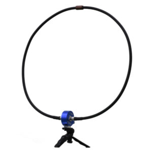
Tekbox TBMA6-P CISPR 16 Passive Loop Antenna 9 kHz – 30 MHz
£932.00 (£1,118.40 inc. VAT)Available on back-order
Availability: Stock models delivered next working day (UK only) for orders placed before 16:30 (Mon - Fri)
Add to basket
-
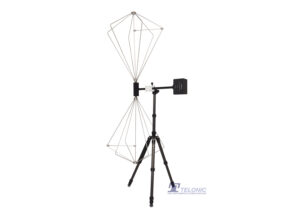
Tekbox TBMA2 Biconical Antenna 30MHz to 300MHz
£933.00 (£1,119.60 inc. VAT)2 in stock (can be backordered)
Availability: Stock models delivered next working day (UK only) for orders placed before 16:30 (Mon - Fri)
Add to basket
-
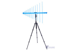
Tekbox TBMA3 250MHz to 1.3GHz LOG Periodic Measurement Antenna
£1,167.00 (£1,400.40 inc. VAT)2 in stock (can be backordered)
Availability: Stock models delivered next working day (UK only) for orders placed before 16:30 (Mon - Fri)
Add to basket
-
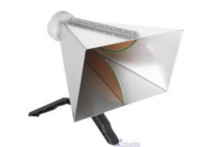
Tekbox TBMA4 CISPR16 1GHz to 8GHz Double Ridged Horn Antenna
£643.00 (£771.60 inc. VAT)3 in stock (can be backordered)
Availability: Stock models delivered next working day (UK only) for orders placed before 16:30 (Mon - Fri)
Add to basket
-
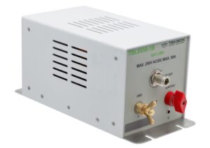
Tekbox TBL0550-1B 5uH 50A Line Impedance Stabilisation Network LISN
£577.00 (£692.40 inc. VAT)Available on back-order
Availability: Stock models delivered next working day (UK only) for orders placed before 16:30 (Mon - Fri)
Add to basket
-
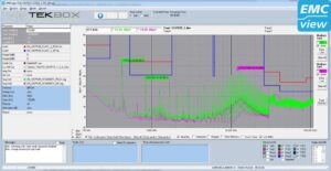
TEKBOX EMCview Pro PC Software Licence
£653.00 (£783.60 inc. VAT)Available on back-order
Availability: Stock models delivered next working day (UK only) for orders placed before 16:30 (Mon - Fri)
Add to basket
Commercial, MIL and automotive: what changes
Commercial: applicable CISPR/EN method, defined distance, antenna and detectors.
MIL: exact MIL-STD-461 requirement, platform, ground plane, antenna and cable geometry.
Automotive: CISPR/OEM method, harness layout, artificial networks, loads and conductive reference plane.
Verify every detail against the controlling edition and laboratory test plan.