 FREE SHIPPING £75+
 CELEBRATING 50+ YEARS
 PRICE MATCH GUARANTEE


Reliable radiated-emissions pre-compliance starts with a repeatable setup. The aim is not to recreate an accredited chamber on a small budget. It is to produce measurements that are consistent enough to identify problem frequencies, compare design changes and reduce the risk of an unexpected formal-test failure.
Start with a defined measurement purpose: relative troubleshooting, margin estimation or correlation with a previous chamber result.
Core equipment
Spectrum analyser or EMI receiver
Choose an instrument that covers the required frequency range and provides suitable resolution bandwidth, detectors, trace storage and correction functions. For initial troubleshooting, a capable spectrum analyser may be sufficient. Work that must closely follow a standard may require EMI-specific bandwidths and detectors.
Calibrated antennas
Use an antenna suitable for the frequency range and measurement distance. Calibration data provides the antenna factor needed to convert the analyser reading into field strength. Uncalibrated antennas remain useful for relative fault-finding, but their results should not be presented as traceable field-strength measurements.
Cables, preamplifiers and attenuation
Use low-loss coaxial cable with known loss versus frequency. A preamplifier can improve sensitivity when the signal is low, while attenuation may be needed to protect the analyser from strong ambient signals. Record every gain and loss in the signal chain.
Positioning and test geometry
An insulated antenna support, a repeatable DUT position and a way to rotate the product make it easier to locate the maximum emission. A wooden table and suitable reference ground plane may be required by the intended setup. Keep metal objects and uncontrolled cable routes away from the measurement path.
Useful additions
- Near-field probes for locating sources on a PCB or cable.
- An RF current probe for identifying common-mode cable currents.
- A comb generator or known reference source for checking the measurement chain.
- A VNA for characterising filters, cables, antennas and impedance-control components.
- Software for segmented sweeps, correction tables, limit lines and repeatable reports.
Before the first measurement
- Confirm the applicable standard, frequency range and measurement distance.
- Collect antenna-factor, cable-loss and preamplifier-gain data.
- Document the DUT operating mode, peripherals, cable routing and power arrangement.
- Run a DUT-off ambient scan and note persistent broadcast or communications signals.
- Take photographs or measurements of the setup so it can be recreated.
-
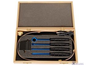
TEKBOX TBPS01-TBWA2/20dB Near Field Probe Set
£307.00 (£368.40 inc. VAT)Available on back-order
Availability: Stock models delivered next working day (UK only) for orders placed before 16:30 (Mon - Fri)
Add to basket
-
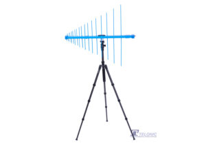
Tekbox TBMA3 250MHz to 1.3GHz LOG Periodic Measurement Antenna
£1,167.00 (£1,400.40 inc. VAT)2 in stock (can be backordered)
Availability: Stock models delivered next working day (UK only) for orders placed before 16:30 (Mon - Fri)
Add to basket
-
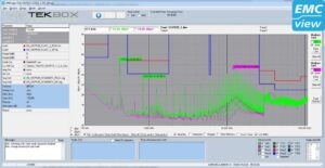
TEKBOX EMCview Pro PC Software Licence
£653.00 (£783.60 inc. VAT)Available on back-order
Availability: Stock models delivered next working day (UK only) for orders placed before 16:30 (Mon - Fri)
Add to basket
-
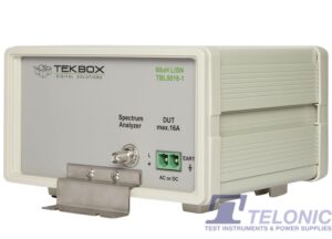
TEKBOX TBL5016-1 50uH 16A Line Impedance Stabilisation Network LISN, CISPR 16-1-2, MIL-STD-461F
£578.00 (£693.60 inc. VAT)Available on back-order
Availability: Stock models delivered next working day (UK only) for orders placed before 16:30 (Mon - Fri)
Add to basket