 FREE SHIPPING £75+
 CELEBRATING 50+ YEARS
 PRICE MATCH GUARANTEE


Electromagnetic compatibility testing is much easier to manage when emissions problems are found during development rather than at the test house. A spectrum analyser gives engineers a frequency-domain view of unwanted energy, helping them identify problem frequencies, compare operating modes and check whether a design change has improved the result.
A spectrum analyser is not a complete compliance laboratory, but with the right settings and supporting equipment it can form the centre of a useful EMC pre-compliance bench.
What a spectrum analyser adds to EMC troubleshooting
- Visibility: separate narrowband clock-related emissions from a raised broadband noise floor.
- Repeatability: save traces and compare the same operating mode before and after a design change.
- Prioritisation: identify frequencies closest to a limit or most likely to cause problems during formal testing.
- Diagnosis: combine the analyser with a LISN, near-field probe, current probe or antenna to trace the likely coupling path.
The analyser capabilities that matter
Resolution bandwidth and frequency spacing
Resolution bandwidth affects both selectivity and the displayed noise level. EMC standards specify bandwidths for different frequency ranges, so a full-span default sweep is rarely suitable. The sweep must also contain enough measurement points that significant signals do not fall between widely spaced frequency bins.
Where one sweep cannot provide the required spacing, divide the measurement into consecutive spans and combine the results. EMC automation software can perform this segmented sweep and present the result as a single trace.
Frequency range and displayed noise floor
The analyser must cover the frequency range required by the product and applicable standard. Its displayed average noise level must also be low enough to reveal emissions below the target limit after probe, antenna, cable and preamplifier effects are considered.
Detectors and measurement time
Peak detection is useful for fast exploratory scans because it quickly identifies the worst frequencies. Quasi-peak and average measurements are then applied where required by the relevant standard. Quasi-peak measurements can be slow, so a practical workflow is to scan with peak detection first and remeasure selected frequencies with the required detector while allowing for frequency drift.
Input attenuation and preamplification
Low attenuation and a preamplifier improve sensitivity, but strong signals can overload the analyser and create misleading internal distortion products. Conducted-emissions setups often encounter large signals, while radiated troubleshooting may need maximum sensitivity. Recheck suspicious peaks with a different attenuation setting: a genuine signal and an analyser-generated product will not always respond in the same way.
A practical pre-compliance workflow
- Define the frequency range, bandwidth, detector and limit required by the relevant standard or test plan.
- Connect the appropriate transducer: LISN for conducted mains emissions, RF current probe for cable current, near-field probe for local diagnosis, or calibrated antenna for radiated measurements.
- Record an ambient or equipment-off trace where applicable.
- Configure attenuation and preamplification so the noise floor is useful without overloading the front end.
- Run a peak scan in manageable frequency segments and mark the highest or closest-to-limit emissions.
- Remeasure the critical frequencies using the required detector and measurement time.
- Save the settings, correction data, trace and equipment configuration so the result can be repeated.
Common setup mistakes
- Using the analyser’s full-span default settings without checking RBW, frequency spacing or sweep time.
- Treating a probe or antenna as flat when its correction changes with frequency.
- Ignoring cable loss, preamplifier gain or attenuator loss.
- Turning on a preamplifier in the presence of strong signals without checking for overload.
- Comparing an uncorrected bench trace directly with a compliance limit.
- Changing the DUT mode, cable routing or grounding between measurements.
-
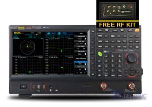
Rigol RSA5032N 3.2GHz Real-Time Spectrum Analyser + VNA
£4,600.00 (£5,520.00 inc. VAT)Available on back-order
Availability: Stock models delivered next working day (UK only) for orders placed before 16:30 (Mon - Fri)
Add to basket
-
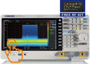
Siglent SSA3050X-R 9kHz to 5GHz Real-Time Spectrum Analyser with VNA and DTF included
£6,317.00 (£7,580.40 inc. VAT)Available on back-order
Availability: Stock models delivered next working day (UK only) for orders placed before 16:30 (Mon - Fri)
Add to basket
-
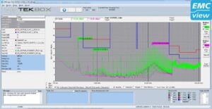
TEKBOX EMCview Pro PC Software Licence
£653.00 (£783.60 inc. VAT)Available on back-order
Availability: Stock models delivered next working day (UK only) for orders placed before 16:30 (Mon - Fri)
Add to basket
Download the detailed application note
This page summarises the main decisions involved in using a spectrum analyser for EMC work. The detailed Tekbox application note by Michael Mayerhofer includes further discussion of CISPR bandwidths, sweep segmentation, detector behaviour and analyser dynamic range.