Beginners who have never used an electronic load may well get confused with the difference between electronic loads and power supplies. They sometimes wonder ‘why the electronic load does not provide any output…?’
While similar in appearance, electronic loads are totally different from power supplies. It is not often you get to see them but it is suitable for specific applications such as working as variable resistors, in a part of high-power systems, to test power supplies.
From here we offer a great series of white papers that give you a thorough understanding of the basics and use of electronic loads, ranged from what it is through to how it is used including its operating principle. Part 1 explores the fundamentals of electronic loads.
* This series focuses on explaining DC electronic loads only; AC electronic loads will not be included.
1. Fundamentals of DC Electronic Load
DC electronic loads are used in a range of DC power supply tests. We will discuss why they are ideally suited for power source testing, in contrast with a popular device, DC power supply.
1-1. Electronic Load and Load of Horse-Drawn Vehicle
Electronic loads can help you investigate the ability of power supplies. This can be compared to the method of determining an ability of a cart horse. Figure 1-1 shows that the horse is pulling the cart of mass 490 kg (approx.1080 lb). If the horse cannot pull a cart of mass 500 kg (approx. 1102 lb), it proves that this horse has the ability of pulling the cart up to 490 kg (approx.1080 lb).

You now understand how electronic loads are different from power supplies; power supplies apply a voltage to DUTs, while electronic loads sink a current from DUTs. So you can now really understand the answer to ‘why electronic loads do not provide any output…?’
1-2. Act as Substitute for High-Power Components
Electronic loads are used to test power source devices. According to Ohm’s law, if the resistor is connected to the output of the power source device (DUT), the current flows from the DUT (See Figure 1-3). Electronic loads can be used as substitute for the resistor. Furthermore, users can easily adjust the resistance value on their own from electronic loads.

In other words, electronic loads can act as a variable resistor, and also achieve tens of kilowatts of power. Instead of using different sizes of fixed resistors, one unit of electronic load allows you test the load dynamically in a repeatable fashion.
Electronic load circuits regulate the resistance value. Based on the performance of circuit functions, electronic loads behave like a 1) Variable resistor 2) Variable Zener diode 3) Load simulator, which described in more detail in the following sections.
1) Act as Variable Resistor
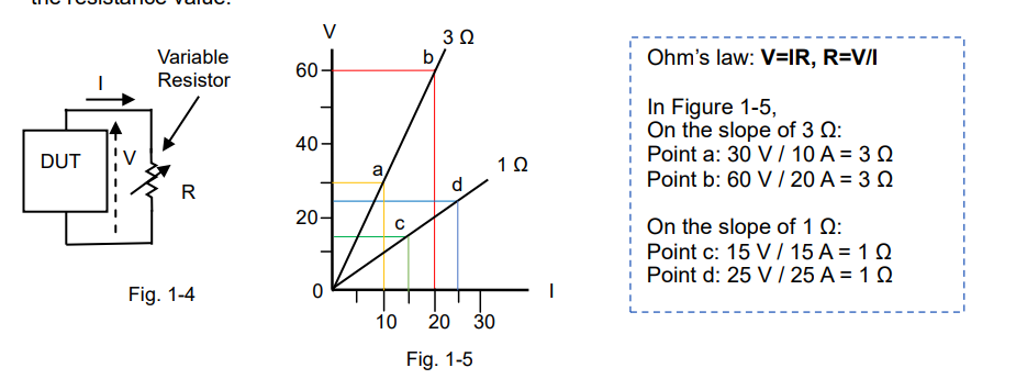
Figure 1-4 shows that the variable resistor is connected to the DUT.
Figure 1-5 shows the relationship between the voltage (V) across the resistor and resistor’s current (I). This relationship in a circuit of the resistor produces a straight line. In the graph, the resistance (R) is the slope. The slope varies according to the resistance value.
During the DC power supply tests, the electronic load controls the resistor’s current by adjusting the resistance value.

The most important aspect is that “the variable resistor can regulate the current flow in the circuit.” If the electronic load acts as a variable resistor, it means that you can control the current based on your test applications or conditions with electronic loads. Furthermore, electronic loads have a capability to provide a constant power or constant current mode, which are described in the next article.
2) Act as Variable Zener Diode
Figure 1-6 shows that the Zener diode is connected to the DUT.
Figure 1-7 shows the relationship between the voltage across the Zener diode and its current. Once the voltage reaches a certain point known as the Zener voltage (Vz), the Zener resistance dramatically decreases. The Zener diode clips any voltage that exceeds the Zener voltage (Vz). In an electronic load, you can set a voltage (equivalent to the Zener voltage) that remains constant regardless of changes to its input current (I). This set voltage is called the constant voltage (CV) and this operation is called the CV mode.

If the DUT is motor in figure 1-6, the DUT may provide a regenerative power by reversing the direction of the motor rotation and it may cause a reverse voltage spike. To prevent it, set the CV voltage so that the voltage will not exceed this CV set voltage.
3) Act as Load Simulator
High-performance electronic loads can simulate various power states so they can be used in diverse applications instead of using a real load. You just select an appropriate electronic load that can exactly simulate your actual load with the waveforms in the example below;
Figure 1-8 shows that the test waveform current flows on a circuit.
Figure 1-9 shows the current waveform simulation example for lamp current.
Figure 1-10 shows the pulsed current waveform simulation example.

Products Mentioned In This Article:
Kikusui Electronic Loads please see HERE


 FREE SHIPPING £75+
 CELEBRATING 50+ YEARS
 PRICE MATCH GUARANTEE


