 FREE SHIPPING £75+
 CELEBRATING 50+ YEARS
 PRICE MATCH GUARANTEE


Unique waveform reproduction technology
RIGOL’s newest arbitrary waveform generators, the DG800 and DG900 Series, combine high resolution output and advanced filtering techniques in point-to-point waveform generation expanding the value of arbitrary waveform generators in test platforms. The DG800 and DG900 (shown in Figure 1) each have our new 16 bit output capability which improves the accuracy of each step in a waveform. Customisable filtering gives you more options to define how these points go together. Without recreating the waveform points change the bandwidth of a signal by precisely defining the high frequency edges. This is the essence of SIFI II technology and it makes RIGOL’s new generators some of the most customisable generators available today.
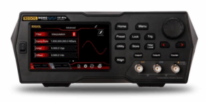
Figure 1: Rigol DG900 Series Waveform Generator
High Resolution with 16 bits
Output resolution is an important characteristic of any signal generator. On modern, digital instruments resolution is measured in bits. Let’s look at a common example. Assume your signal generator has a 10 Vpp output. If the voltage level within that 10 volt swing is represented by a 14 bit number, that means that there are 2^14 or 16,384 possible output values. These are then distributed evenly so 10 volts divided by 16,384 means that each level is 610 microvolts from its neighbour. If the desired voltage level at a point in time is really between two of these levels then one level is selected as the closest option. This creates a small error in relation to the desired signal. Over time this error can make a substantial difference to the signal fidelity and ultimately to the response of the device under test.
With a 16 bit generator the same 10 volt swing is split into 2^16 or 65,536 sections. Since each of the additional bits has 2 states (0 or 1) there are 4 times as many states in a 16 bit number. With 4 times as many voltage settings available the error introduced is significantly reduced. But that isn’t the only effect. Since there are more voltage options the instrument is more often able to adjust the output taking advantage of its output rate.
Let’s take a look at how these two signals compare with an oscilloscope. Figure 2 shows the averaged waveforms from the 14 and 16 bit output. Figure 3 shows an arbitrary wave that we have created for this test. It is a standard 8192 point arbitrary wave that includes a slow ramp in voltage followed by a pulse to -5 V and then to 5 V.
The purpose of the pulse activity is to make certain the generators we test are setting their output range correctly for 10 Vpp. We loaded this same arbitrary wave into two instruments. One is a 14 bit generator and one is the new DG900 Series 16 bit generator. We synchronised the outputs and set each instrument to output 1 MSample per second to make the minimum step time 1 microsecond. We then captured the outputs of both generators on the oscilloscope using heavy averaging. This reduced the noise and enabled us to view the output steps of each instrument. The oscilloscope screen is the comparison shown in Figure 2.
The purple trace is the 14 bit generator. As you can see the output changes every 6 microseconds. Even though the output is set to change every microsecond the slow ramp in the arbitrary wave only moves enough in voltage every 6 steps to trigger an actual level change in the output.
The 16 bit channel in yellow is using the same arbitrary wave file. Because the output has a smaller voltage step size it makes smaller steps and also makes them more frequently since the voltage change requested in the waveform file is 4 times as likely to trigger a change. Under these test conditions the 16 bit generator updates the output about 4 times as often and each step has 4 times the resolution.
To analyse this data further we can request it from the scope and chart it in Excel (shown in Figure 4). Here we show the data extracted from the oscilloscope for the two channels as well as the ideal ramp line we were trying to emulate, all overlaid. As shown in the inset, the RMS error of each waveform is calculated in comparison to the ideal line. The 16 bit generator reduces the RMS error of the signal by a factor greater than 2 meaning that is contains less than half the RMS error.
In cases where accuracy and signal fidelity are important, the RIGOL 16 bit generators provide significantly more capability than traditional 14 bit generators.
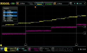
Figure 2: 14 bit vs 16 bit Oscilloscope comparison
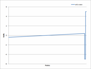
Figure 3: Sample Arbitrary Waveform
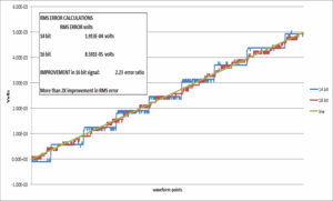
Figure 4: Comparison of emulated and ideal signals showing > 2x RMS error improvement with 16 bits
Flexibility in Filtering with SiFi II
While the 16 bit resolution improves signal fidelity, how an instrument moves between points in a waveform has a dramatic effect on both the time domain and RF domain view of a signal’s characteristics. Traditional generators employed DDS (Direct Digital Synthesis) technology which selects the best output point at any time based on phase. RIGOL’s SiFi technology, which was introduced on the DG1000Z series generators employs a true point-to-point output to decrease overall signal noise versus DDS.
The DG800 and DG900 Series generators are the first generators to employ SiFi II technology. These instruments utilise the point-to-point accuracy of SiFi and add filter customisation to the movement between points. This customisable setting provides flexibility for dynamic signal generation. Within the sequence menu users can select between interpolation, step, and smooth filtering. These filtering techniques change the look of the waveform in time and RF domains in ways that aren’t easy to duplicate without starting over with a new waveform on any other generator. Let’s look at a simple 1 kHz square wave. Using the standard square wave function in sequence mode utilises an 8,192 point square wave. In the sequence menu we set 8.192 MSamples per sec so that the wave repeats every 1 millisecond. Now, we can use the same wave amplitude and points in a point by point mode, but alter the output by adjusting the filtering. Figure 5 shows how the different filtering options appear on a spectrum analyser. Using a max hold trace we can see how much wideband noise is generated by each method.
Even though the primary signal is only at 1 kHz the square wave generates harmonics viewable out in MHz. By changing the filtering mode engineers can create a sharper drop-off indicative of a filtered or bandwidth limited signal path or a wide bandwidth footprint can be selected. This capability is very useful for looking at how signal conditioning and system design might affect the interpretation of the generated signal. Figure 6 shows the same 3 signals on an oscilloscope. The step filter creates a near ideal step response with limited overshoot. Consequently, there are fewer high frequency components present. The smoothing filter smooths the transitions but allows for some overshoot creating a different time domain look and a moderate amount of high frequency components. Interpolation mode creates a linear step. This step function has hard edge transitions that add significant high frequency components. The edge time in interpolation mode can be adjusted for further optimisation. We can see this in Figure 7. Here we used infinite persistence on the oscilloscope to show that the edge time can be set from 8 ns to about 90 ns in this configuration. This gives system engineers a tool for fine tuning signal response to verify their design parameters. With all of these filtering options the generated signal can be optimized to closely match whatever signal characteristics are required.
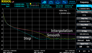
Figure 5: Comparison of SiFi II filter modes in the frequency domain
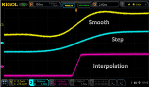
Figure 6: Comparison of SiFi II filter modes in the time domain
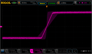
Figure 7: Range of the edge time in interpolation filter mode using SiFi II technology
Unprecedented Value
RIGOL’s SiFi II technology and the DG800 and DG900 series waveform generators allow engineers to more closely reproduce signals of interest with a combination of 16 bit resolution and point to point filtering options. Signals with complex RF footprints or high fidelity requirements can now be emulated more precisely with RIGOL’s SiFi II technology in the DG800 and DG900 series arbitrary waveform generators
Products Mentioned In This Article: