Power supply has the following three output terminals:
– DC power supply: Positive/negative terminals and Ground (GND) terminal – AC power supply: L/N terminals and GND terminal.
Upon using both power supplies, it is necessary to determine whether either of positive or negative terminals or L/N terminals is connected to the GND terminal.
As our factory default;
– DC power supply: Depending on the series or models, the GND terminal is connected to the negative terminal or floating (non-grounding).
– AC power supply: The GND terminal is floating.
The following information may help you to ground the power supply properly.
1. Isolation Block Diagram for Each Terminal
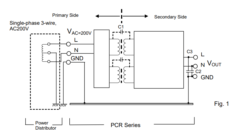
Figure 1 shows how the output (secondary) terminals of AC power supply are isolated from the input (primary) terminals and the GND terminal. The isolation block terminal for DC power supply can be compatible to Fig. 1.
Figure 1 provides the example as: single-phase three-wire, AC200V.
1) The GND terminal at the output side is connected to the GND terminal at the input side. The GND terminal at the input side is required to be grounded by connecting to the ground terminal at the distribution board for safety reasons. If not, please make sure to check the condition of EUT.
2) The output terminals except for the GND terminal are isolated from the input terminals. Isolation is specified in specifications. E.g.) Withstand voltage between the primary and secondary side is AC1500V/1 mins.
2. Requirement and Effect on Grounding Output Terminal
The requirement and effect on grounding are described in each subsection with case studies.
2-1 Electric Shock Caused by Isolated Power Supply
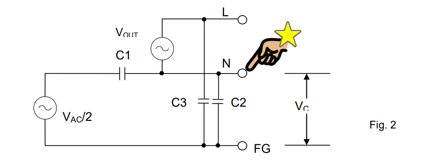
The following inquiry might be asked: ‘Why did I have an electric shock when I touched the N terminal even the AC power supply is isolated?’
As shown in Figure 1 above, the primary and secondary terminals of power supply are isolated. However, Figure 2 shows that the voltage is divided at the capacitance of C1/C2 and applied to the N terminal. In this case, you may have an electric shock when touching the N terminal.
To avoid this issue, please connect the N terminal to the GND terminal or connect a high-capacity capacitor between the N terminal and the GND terminal.
2-2 Power Supply for Swimming Pool Water Treatment
Figure 3 shows the equivalent circuit of the swimming pool water purification system. As you can see, the output from the DC power supply is in the swimming pool. If the isolation between the primary and secondary terminals is not fully secured due to any trouble, the voltage from the primary terminals will be applied into the water. Then, it induces the leakage current into the swimming pool and it may cause an electric shock.
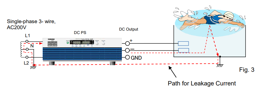
To avoid this issue, please always connect either of positive or negative output terminals to the GND terminal. For the case of 2-1 and 2-2, the grounding is required at the secondary terminals for safety.
2-3 Power Supply for Wireless Transmitter (Ground Connection at High-Frequency)
Figure 4 shows the system that measures the wireless transmitter power. Common-mode noise is generated inside the power supply. In this figure, the output terminals of power supply are connected to the wireless transmitter. Common-mode noise is emitted to the surroundings as shown by the arrow. When the common-mode noise passes through the ground loop, it turns to the current noise (I-noise). Then, when this current noise passes through the cable outer coating, VI will be generated and measured by the spectrum analyser.
To avoid this issue, the output terminal of power supply is connected to the GND terminal to eliminate the common-mode noise.

2-4 Leakage Current Test
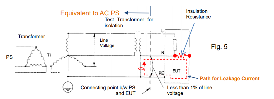
Figure 5 is referred to the IEC60990 that defines the measurement of leakage current (protective conductor current and touch current). This circuit is equivalent to the measuring of the leakage current when the AC power supply is connected to EUT. In this case, the N terminal should be connected to PE (Protective Earthing = GND terminal) to create the path for leakage current as shown by the red dotted lines.
Since either of output terminals should be grounded to measure the leakage current, AC power supply is suitable for such measurement.
3. Consideration for Voltage to Ground
Voltage to ground is specified for output terminals by product series/models. It means the maximum voltage to be applied between the output terminals (positive/negative or L/N) and GND terminal (chassis potential). In Figure 6, neither V (N-G) nor V (L-G) can exceed the voltage to ground.
For the figures below, if you use the DC power supply, please regard L terminal as positive terminal and N terminal as negative terminal.

Please be noted that the output voltage applied to the output terminals and GND terminal might be limited depending on the power supply specification.
Two examples are listed below with the condition as: Using DC power supply with Rated output voltage= DC300V and Voltage to ground=±DC500V.
Example 1: If DC250V is applied between N and GND, the output voltage (VOUT) is limited to DC250V.
VOUT = Voltage to ground – V (N-G) = 500V – 250V = 250V
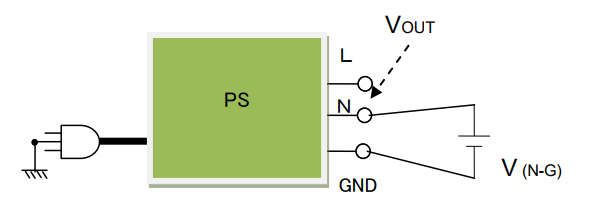
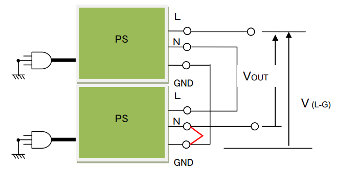
Example 2: Two DC power supplies are connected in series and the N terminal and GND terminal at the second power supply are connected. V (L-G) is DC500V so that the VOUT is limited to DC500V even with two power supplies used.
