Solution: This application note is designed to show FM data transmission and modulation using some common test instruments.
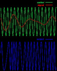
An FM transmission consists of a wave who’s frequency is modulated, or changed, with respect to an input signal. If the input signal frequency changes, so does the carrier frequency.
The modulating signal affects the FM deviation. The total deviation is a function of the modulating signal’s frequency and amplitude.
Here is a typical FM signal shown on an amplitude vs. time graph.
In this demonstration, we are going to use an arbitrary waveform generator to create an FM signal. The FM signal will be modulated by a audio source.
This signal will be transmitted from the output of the generator through an antenna to the input of a spectrum analyser. There, the signal will be displayed on the spectrum analyser, demodulated, and played back through the internal speaker of the instrument.
Required Hardware:
1. A Spectrum Analyser with demodulation capabilities: The Rigol DSA800, 1000, and 1000A series of spectrum analysers all support this function. This demo will use the DSA-1030A, but the process is basically the same.
2. Arbitrary Waveform Generator: Rigol’s DG4000 series is perfect for this experiment. We use the DG4162 160MHz model in this demo.
3. Music source with a headphone jack. In this demo, we will use a cell phone with music source.
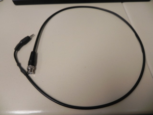
4. Adapter cable from music source to BNC cable. In this demo, we made a cable by splicing a 3.5mm audio jack to a 50 ohm coaxial cable with a BNC termination.
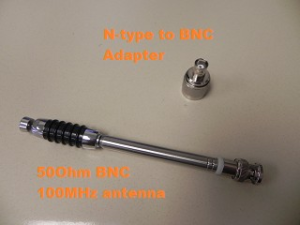
5. N-Type to BNC adapter. This is used to adapt the DSA input to the antenna.
6. Qty 2 FM Radio Antennas with matching frequency ranges. In this demo, we use (2) BNC terminated center loaded whip antennas from Radio Shack.
Configure the Arbitrary waveform generator:
In this setup, we want to use the Sine function of the arbitrary waveform to create the carrier wave that supports the signal that we want to transmit and . The audio input signal will be used to modulate the carrier frequency by the deviation that we set.
In the US, commercial radio stations transmit from 87.9 to 107.9MHz. The FM deviation, or amount that the carrier frequency is modulated, is less than or equal to 150kHz, or +/- 75kHz around the carrier frequency.
1. Power on the DG4000.
2. Connect the BNC-to-Phone jack to the CH1 Mod/FSK/TRIG input on the back of the DG4000.
3. Connect the antenna to the Channel 1 output.
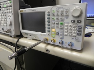
4. Connect your music source and start the music. Make sure to enable the sound on the device.. check that the volume level is > 0.
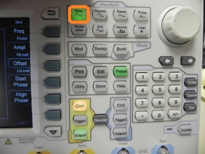
5. Configure the DG4000 to output a sine by pressing Sine on the Waveform area of the front panel.
6. Set the frequency of the sine wave to 100.00MHz.
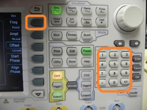
NOTE: You may need to change the frequency by a few 100kHz, if the local radio stations are interfering with the band you are transmitting in. You can simply change the carrier a few 100kHz.
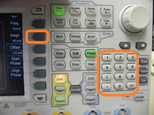
7. Set the amplitude to 2Vpp by pressing the Amp button and then entering 2Vpp on the keypad. Alternately, you can use the scroll wheel to change the values.
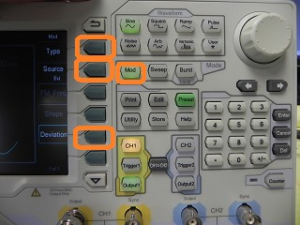
8. Press the Mod key to enable modulation.
• Set type to FM
• Set source to external
• Set deviation to 150kHz
Configure the Spectrum Analyser:
The arbitrary waveform generator is used to create the FM signal and the spectrum analyser is used to capture and demodulate the transmission.
In the US, commercial radio stations transmit from 87.9 to 107.9MHz. The FM deviation, or amount that the carrier frequency is modulated, is less than or equal to 150kHz, or +/- 75kHz around the carrier frequency.
1. Power on the DSA.
2. Connect the N-type adapter and antenna to the RF input
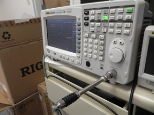
3. BNC-to-Phone jack to the CH1 Mod/FSK/TRIG input on the back of the DG4000.
4. Set the center frequency equal to the carrier frequency of the arbitrary waveform generator. In this example, we have set the DG4000 to output at 100.00MHz.
• Press Freq > Center Frequency > 100.00MHz
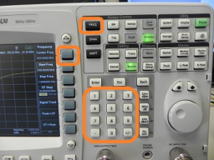
NOTE: You may need to change the frequency by a few 100kHz, if the local radio stations are interfering with the band you are transmitting in. You can simply change the carrier a few 100kHz.
5. Set the span of the DSA to 200kHz.
• Press Span > set span to 200kHz using the keypad
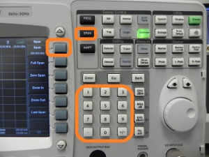
• You should see the signal present on the DSA. You can observe the signal by turning the DG4000 output on and off. The DSA signal should go flat when the DG4000 is off and then rise when the output is on.
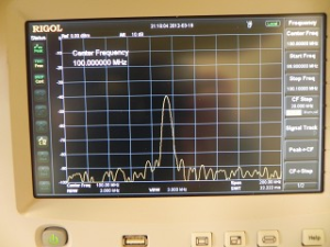
6. Now, we can demodulate the FM signal and listen to the transmission.
• Press Demod
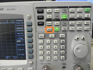
• Enable Demod
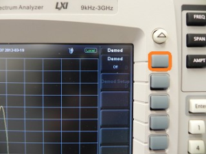
• Press FM
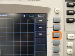
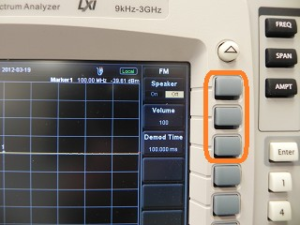
• Press Demod Setup
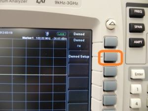
• Turn the Speaker ON
• Set volume to 100
• Set Demo Time to 10s
Products Mentioned In This Article:

















 FREE SHIPPING £75+
 CELEBRATING 50+ YEARS
 PRICE MATCH GUARANTEE

