Solution: Almost any electronic design slated for commercial use is subject to EMC (Electromagnetic Compatibility) testing. Any company intending to sell these products into a country must ensure that the product is tested versus specifications set forth by the regulatory body of that country. Here in the US, the FCC specifies rules on EMC testing. CISPR and IEC are also used throughout the world.
To be sold legally, a sample of the electronic product must pass a series of tests. In many cases, companies can self-certify, but they must have detailed reports of the test conditions and data. Many companies choose to have these tests performed by accredited compliance company. This full compliance testing can be very expensive with many labs charging thousands of dollars for a single day of testing. Testing a product for full compliance can also require specialised testing environments and no changes can be made during the testing. Any failures in compliance testing require that the design heads back to Engineering for analysis and possible redesign. This can cause delays in product release and an obvious increase in design costs.
One method to lower the additional costs associated with EMC compliance is to perform EMC testing throughout the design process well before sending the product off for full compliance testing. This pre-compliance testing can be very cost effective and can be tailored to closely match the conditions used for compliance testing. This will increase your confidence in passing compliance the first time through, lower your test costs, and speed your time to market.
Measuring Radiated EMI
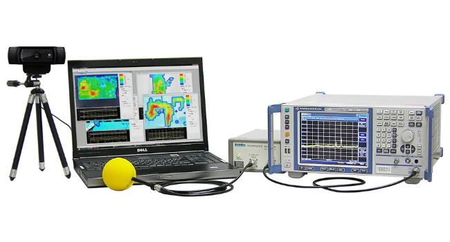
The most simple form of pre-compliance measurements for radiated emissions can be performed using a spectrum analyser, like the Rigol DSA-815 (9kHz to 1.5GHz), and near field electric (E) and magnetic (H) probes.
Figure 1 and 2: Near field E and H probes.
The most simple test is to configure the DSA to use the peak detector and set the RBW and Span for the area of interest per the regulatory requirements for your device. Then select the proper E or H probe for your design and scan over the surface of the design.
Probe orientation (rotation, distance) is also important to consider. The probes act as an antenna, picking up radiated emissions from seams, openings, traces, and other elements that could be emitting RF. A through scan of all of the circuit elements, connectors, knobs, openings in the case, and seams is crucial.
Figure 3: Using a near field H probe to test a power supply.
For the first pass, configure the spectrum analyser to use the peak detector. This will provide you with a “worst case” reading on the radiated RF and it is the quickest path to determining the problem areas. Larger probes will give you a faster scanning rate, albeit with less special resolution.
Once you have a good idea of your problem areas, you can get more detail by implementing a few common techniques. If you can, select a spectrum analyser that has the standard configuration used in full compliance testing. This includes a Quasi-Peak detector mode, EMI filter, and Resolution Bandwidth (RBW) settings that match the full test requirements specified for your product.
This type of setup will increase testing time but should be used on the problem areas. A full compliance test configuration will mean your pre-compliance testing will provide a greater degree of visibility into the EMI profile of your design.
On many instruments, you can also store cable and antenna correction factors that will allow you to see the true signal, without the added errors from the setup.
The next step in radiated testing includes using antennas in place of the near field probes, a rotating platform for the equipment under test (EUT), and can include a special room that minimises environmental factors (semi-anechoic). These setups are beyond the scope of this document, but there are references at the end that provide good references for the details of the setup.
Figure 4: Compliance Setup for Radiated Emissions Testing
Measuring Conducted EMI
Conducted EMI testing requires analysing the RF energy that is coupled from the instrument or test circuit to the main power line it is connected to.
Like Radiated EMI, Conducted EMI is also measured using a spectrum analyser, but it also requires a transient limiter and a Linear Impedance Stabilisation Network (LISN). A LISN isolates the power mains from the equipment under test, isolates any noise generated by the EUT, and couples the signals generated by the EUT to the spectrum analyser.
Figure 3: Standard Conducted Emissions pre-compliance setup via a transient limiter. Note: be sure to choose a limiter suited to your own system and testing regime and do your own checks first: transients can easily exceed the input rating of your analyser (e.g. at switch-on – it is good practice to avoid switching on the LISN with the analyser connected) A modern DSA’s internal level indicator is not intended to warn against fast transients and internal attenuators do not provide greater input circuit protection – if in doubt do your own measurements first to ensure you always operate within the stated input limit envelope.
As with emissions testing, the best start is a scan over the frequency range of interest using the peak detector on the spectrum analyser. Then, performing a quasi-Peak scan using the EMI filter for the problem areas. This will minimise test time while maintaining a high degree of confidence in your test.
Summary
EMC Compliance testing is mandatory for the majority of electronic products that are slated for sale throughout the world. For the cost of 1 day of compliance testing, you can have a pre-compliance setup that you can use to continually monitor and improve your design. This will help speed product development and save the company money.


 FREE SHIPPING £75+
 CELEBRATING 50+ YEARS
 PRICE MATCH GUARANTEE


