 FREE SHIPPING £75+
 CELEBRATING 50+ YEARS
 PRICE MATCH GUARANTEE


An embedded bus can decode correctly on the bench and still fail after the enclosure, flex cable, sensor stack or production wiring is introduced. Signal-integrity testing should therefore establish a repeatable analogue baseline, reproduce what the digital receiver sees and track margin as the mechanical and firmware design changes.
Measure the physical signal before trusting the decode
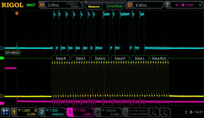
Bandwidth
Confirm edges settle within the available bit time; avoid using clock frequency as the only bandwidth guide.
Noise and crosstalk
Test while other peripherals, radios and power converters are active.
Impedance and loading
Check termination, probe capacitance, ground inductance and connector or flex discontinuities.
Threshold margin
Compare analogue levels with the receiver’s valid-high, valid-low and hysteresis requirements.
Build a repeatable SPI or I²C test
- Probe at the receiver or most vulnerable node, not only beside the controller.
- Capture clock, data, chip-select or enable together with a relevant power rail.
- Use protocol decode to locate transactions, then inspect the analogue waveform around failures or low-margin events.
- Set digital-channel thresholds to represent the receiving logic family when mixed-signal inputs are used.
- Create a mask or measurement limits from a known-good baseline and save them with the setup.
- Exercise worst-case cable position, enclosure state, sensor activity, temperature and supply condition.
Separate a protocol error from its electrical cause
A decoder reports how the oscilloscope interpreted the waveform at its configured threshold. It does not prove that the real receiver saw the same thing. When a decoded error appears, inspect setup/hold timing, edge rate, overshoot, ringing and reference movement. When the decode looks correct but the product fails, compare thresholds, probe location and the receiver’s timing requirements.
Use analogue and digital views together
Analogue channels
Expose noise, slow edges, ringing, droop and coupling that a logic trace hides.
Digital channels
Extend channel count and show how selected thresholds convert the bus into logic states.
Search and decode
Find a specific address, data value, error or long gap inside a deep record.
Masks and statistics
Reveal rare departures and compare board, code or enclosure revisions consistently.
Measure latency as well as correctness
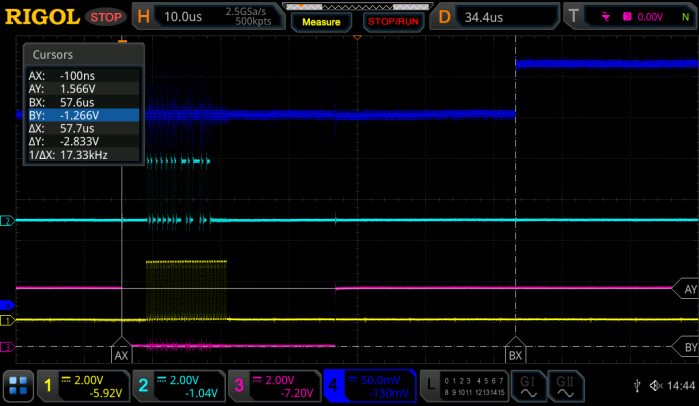
User experience can depend on the delay from sensor transaction to system action. Trigger on the relevant bus event and measure to an application output, interrupt, GPIO marker or current-state change. Store the distribution across many events; one cursor reading may miss scheduling delays and retries.
Recommended instruments
-
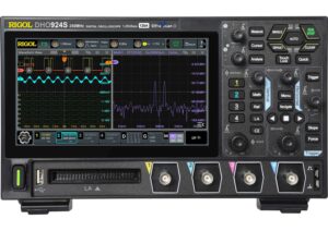
Rigol DHO914 4CH, 12Bit, 125MHz, 1.25GSa/s Digital Oscilloscope
£501.00 (£601.20 inc. VAT)Available on back-order
Availability: Stock models delivered next working day (UK only) for orders placed before 16:30 (Mon - Fri)
Add to basket
-
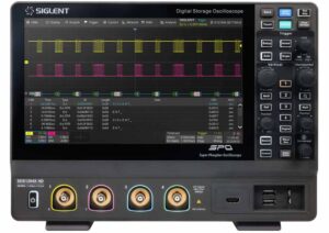
Siglent SDS1104X HD 4Ch, 100MHz, 2GSa/s, 12 Bit, HD high resolution oscilloscope
£926.00 (£1,111.20 inc. VAT)2 in stock (can be backordered)
Availability: Stock models delivered next working day (UK only) for orders placed before 16:30 (Mon - Fri)
Add to basket
-
Sale!
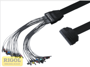
Rigol PLA2216 High-performance Active Logic Probe
Original price was: £277.00.£250.00Current price is: £250.00. (£300.00 inc. VAT)1 in stock (can be backordered)
Availability: Stock models delivered next working day (UK only) for orders placed before 16:30 (Mon - Fri)
Add to basket
-
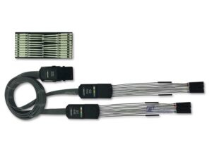
Siglent SPL2016 Logic Probe
£358.00 (£429.60 inc. VAT)5 in stock (can be backordered)
Availability: Stock models delivered next working day (UK only) for orders placed before 16:30 (Mon - Fri)
Add to basket