We have so far explained the four major operation modes for electronic loads – 1) constant current 2) constant resistance 3) constant voltage and 4) constant power, in the previous white papers. Now this paper describes how these modes relate to each other and how each mode works on other modes.
4-1. Relationship between Operation Modes
Figure 4-1 shows the block diagram for the control circuit structure of the electronic loads, where each operation mode is switched by.
The CC-CR switch closes either path of the constant current (CC) circuit or the constant resistance (CR) circuit. There is the OR circuit connected between the closed circuit (either CC or CR), the constant power (CP) circuit and constant voltage (CV) circuit. You will have the following three factors to determine which circuit is used, CP circuit or CV circuit: 1) the setting value for each control circuit 2) the input voltage of the electronic load and 3) the input current of the electronic load. In addition, the setting of the CV-ON switch determines whether to use the CV circuit or not.
Therefore, the electronic load users need to set at least the following settings:
1) Choose the CC mode or the CR mode to be used.
2) Choose whether to use the CV mode or not.
3) Set the appropriate settings for each operation mode.
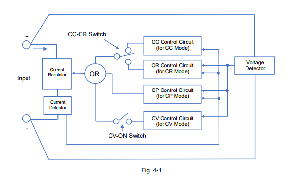
As stated above, the four operation modes have the relationship with each other and the modes are switched depending on the setting values, the input voltage and the input current of the electronic load. In the next sections, we are going to explain the details how each mode is related and when exactly the modes are switched.
4-2. How CC Mode is Combined with Other Mode
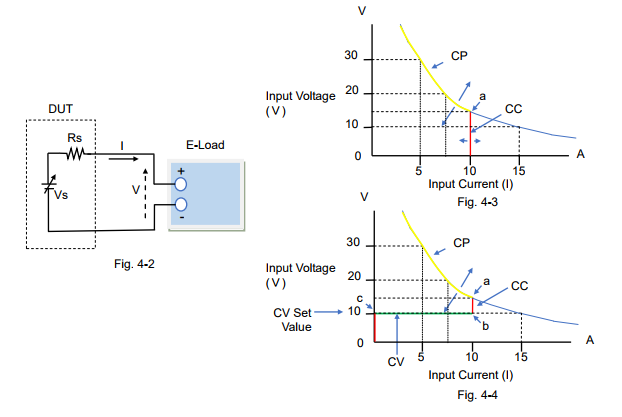
Figure 4-2 describes the circuit of the DUT and the electronic load; the components of the DUT are the voltage source (Vs) such as a power supply and the resistance (Rs) connected in series with Vs.
Figure 4-3 and 4-4 are the characteristic examples of how the input current flows with the Vs change when the CC mode setting of the electronic load is set to 10 A.
For figure 4-3, the CV mode is turned off. While Vs rises from almost 0 V to Point ‘a’, the electronic load operates in CC mode at 10 A as shown in the red line. After Vs exceeds Point ‘a’, the electronic load operates in CP mode*1 at 150 W as shown in the yellow line.
For figure 4-4, the CV mode is turned on (CV-ON). If Vs rises from almost 0 V, the input current does not actually exist until Point ‘c’ (= at the CV set value). After Vs exceeds Point ‘c’, the electronic load operates in CV mode until Point ‘b’, but it operates in CC mode after Point ‘b’ to Point ‘a’ at 10 A. After Vs exceeds Point ‘a’, the electronic load operates in CP mode*1 at 150 W as shown in the yellow line.
*1: Some electronic loads provide the overpower protection (OPP) function instead of the CP mode. The protection function will be described later in another white paper in this series.
Recommendations and Precautions for Use of CC Mode
To ensure the reliability of the CC mode operation, read the following advice:
1) If you want to use the CC mode only, you just set the CC mode setting. Turning off the CV mode is recommended, because if the CV mode is turned on (CV-ON), the input current does not actually exist until the input voltage reaches the CV set value. When setting the CP mode value or the OPP value, set it to the maximum.
2) The CV mode (CV-ON) can be used as the over-discharge protection for rechargeable batteries. Initially the CC mode starts to discharge the battery until the battery voltage falls to the CV set value. Then, the mode switches from CC to CV and the electronic load stops the input current flow. This prevents the battery voltage from becoming too low to protect against over discharge.
3) When entering the CC mode, some electronic loads may automatically set the CP mode value to the maximum.
4-3. How CR Mode is Combined with Other Mode
For the system circuit, see figure 4-2 above.
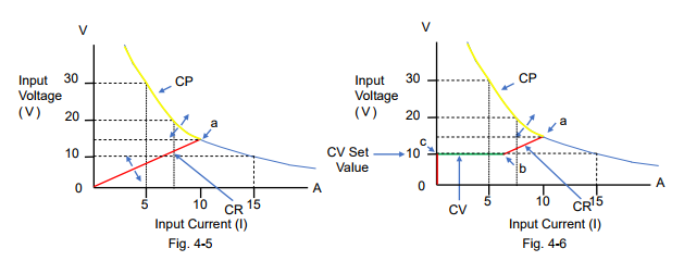
Figure 4-5 and 4-6 are the characteristic examples of how the input current flows with the Vs change when the CR mode setting of the electronic load was set to 1.5 Ω.
For figure 4-5, the CV mode is turned off. While Vs rises from almost 0 V to Point ‘a’, the electronic load operates in CR mode at 1.5 Ω as shown in the red line. After Vs exceeds Point ‘a’, the electronic load operates in CP mode*2 at 150 W as shown in the yellow line.
For figure 4-6, the CV mode is turned on (CV-ON). If Vs rises from almost 0 V, the input current does not actually exist until Point ‘c’ (= at the CV set value). After Vs exceeds Point ‘c’, the electronic load operates in CV mode until Point ‘b’, but it operates in CR mode after Point ‘b’ to Point ‘a’ at 1.5 Ω. After Vs exceeds Point ‘a’, the electronic load operates in CP mode*2 at 150 W as shown in the yellow line.
*2: Some electronic loads provide the overpower protection (OPP) function instead of the CP mode. The protection function will be described later in another white paper in this series.
Recommendations and Precautions for Use of CR Mode
To ensure the reliability of the CR mode operation, read the following advice:
1) If you want to use the CR mode only, you just set the CR mode setting. Turning off the CV mode is recommended, as stated above in ‘Recommendations and Precautions’ of Section 4-2. When setting the CP mode value or the OPP value, set it to the maximum.
2) The CV mode (CV-ON) can be used as the over-discharge protection for rechargeable batteries. For this CV mode operation, refer to ‘Recommendations and Precautions’ of Section 4-2. *Read as changing the CC mode to the CR mode.
3) When entering the CR mode, some electronic loads may automatically set the CP mode value to the maximum.
4-4. How CP Mode is Combined with Other Mode For the system circuit, see figure 4-2 above.
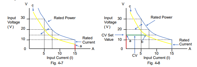
Figure 4-7 and 4-8 are the characteristic examples of how the input current flows with the Vs change when the CP mode setting of the electronic load was set to 100 W.
For figure 4-7; the CV mode is turned off, and the CC mode or the CR mode is set to Automatic or the maximum rating value. If Vs rises from almost 0 V to Point ‘a’, the electronic load operates in CC mode at 15 A (rating current) as shown in the red line. After Vs exceeds Point ‘a’, the electronic load operates in CP mode at 100 W as shown in the yellow line and it may reach Point ‘c’ with Vs change.
For figure 4-8, the CV mode is turned on (CV-ON). While Vs rises from almost 0 V, the input current does not actually exist until Point ‘a’ (= at the CV set value). After Vs exceeds Point ‘a’, the electronic load operates in CV mode until Point ‘b’. After Vs exceeds Point ‘b’, the electronic load operates in CP mode at 100 W as shown in the yellow line and it may reach Point ‘c’ with Vs change.
Recommendations and Precautions for Use of CP Mode
To ensure the reliability of the CP mode operation, read the following advice:
1) When setting the CP mode value and the CR mode value, set them to the maximum.
2) If you want to use the CP mode only, you just set the CP mode setting. Turning off the CV mode is recommended, as stated above in ‘Recommendations and Precautions’ of Section 4-2.
3) The CV mode (CV-ON) can be used as the over-discharge protection for rechargeable batteries. For this CV mode operation, refer to ‘Recommendations and Precautions’ of Section 4-2. *Read as changing the CC mode to the CP mode.
4) In CP mode, if you do not want a high input current, you can regulate it by setting a lower CC mode value or setting an overcurrent protection (OCP).
4-5. How CV Mode is Combined with Other Mode For the system circuit, see figure 4-2 above.
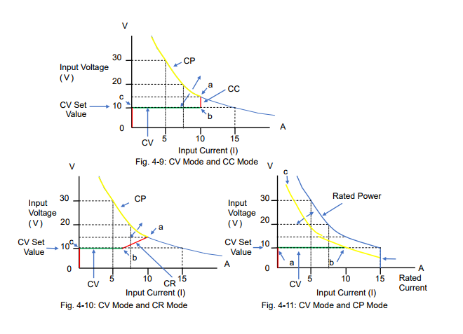
Figure 4-9, 4-10 and 4-11 are the characteristic examples of how the input current flows with the Vs change when the CV mode setting of the electronic load was set to 10 V.
Figure 4-9 shows the combination between the CV mode and the CC mode. For the CV mode operation, read Section 4-2 describing figure 4-4 ‘the CV mode is turned on (CV-ON)’. The input current does not actually exist until Vs reaches the CV set value. After Vs exceeds Point ‘c’, the electronic load operates in CV mode until Point ‘b’ as shown in the green line. Then, after Vs exceeds Point ‘b’, the mode switches to the CC mode until Point ‘a’. If Vs rises above Point ‘a’, the mode switches to the CP mode*4.
Figure 4-10 shows the combination between the CV mode and the CR mode. For the CV mode operation, read Section 4-3 describing figure 4-6 ‘the CV mode is turned on (CV-ON)’. Figure 4-10 looks similar to figure 4-9, except that the mode is in the CR mode from Point ‘b’ to Point ‘a’. Figure 4-11 shows the combination between the CV mode and the CP mode. For the CV mode operation, read Section 4-4 describing figure 4-8 ‘the CV mode is turned on (CV-ON)’. While Vs is lower than Point ‘a’ (= at the CV set value), the input current does not actually exist. When Vs exceeds Point ‘a’, the electronic load operates in CV mode until Point ‘b’ as shown in the green
line. After Vs exceeds Point ‘b’, the electronic load operates in CP mode.
*3: ‘CV-ON’ can be referred to as ‘+CV’.
*4: Some electronic loads provide the overpower protection (OPP) function instead of the CP
mode. The protection function will be described later in another white paper in this series.
Products Mentioned In This Article:
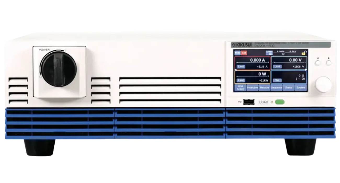
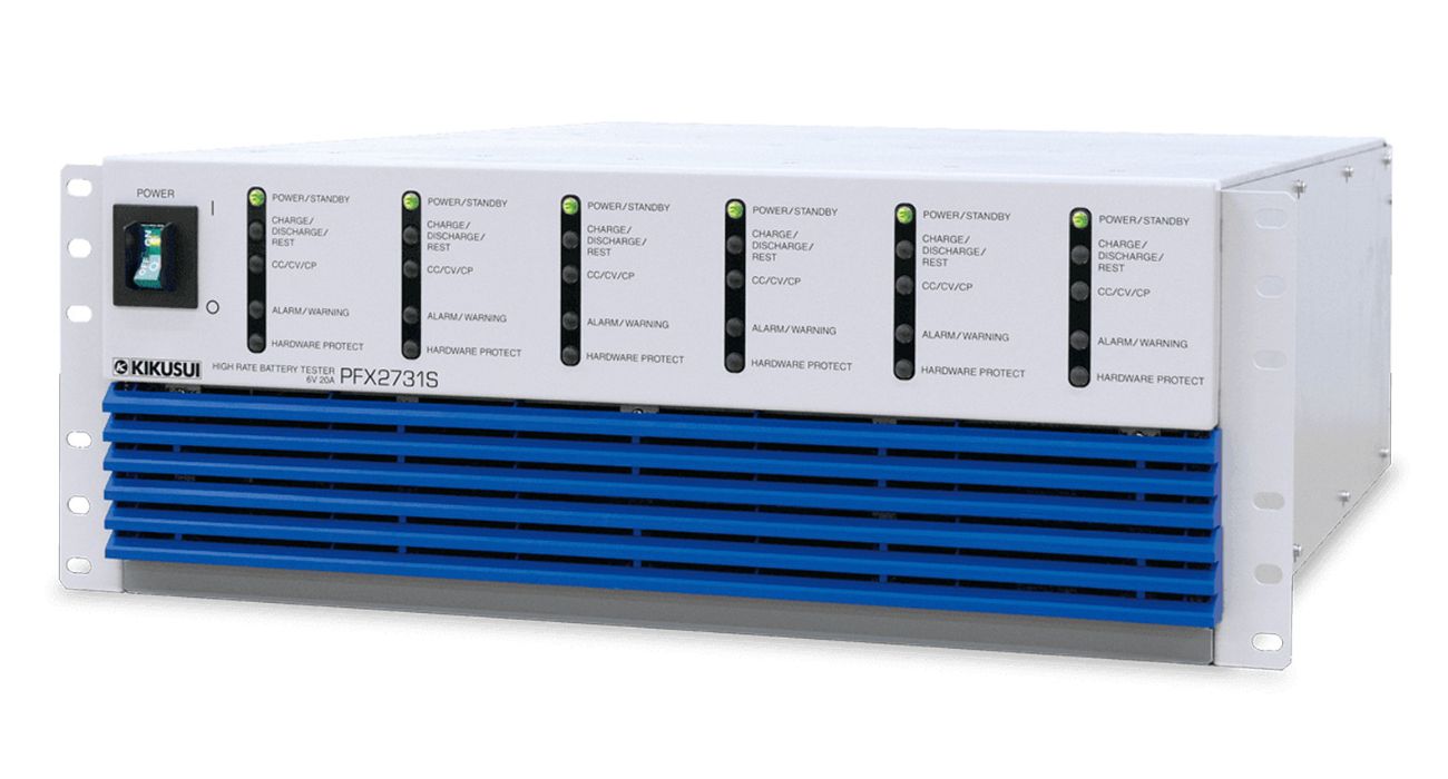
Kikusui Electronic Loads please see HERE
















 FREE SHIPPING £75+
 CELEBRATING 50+ YEARS
 PRICE MATCH GUARANTEE

