Wireless Communication and Function
The internet of Things (IoT) is one of the fastest growing areas of technology today. In this increasing competitive field, the greatest challenge facing IoT device manufacturers is determining how to create the smallest devices possible without sacrificing performance in terms of range or power. For IoT devices that utilise radio frequency (RF) communication, one of the greatest opportunities to improve the design of the device while also improving the range and quality; that is, it provides the greatest possible range given the available power and size constraints.
Determining Operating Frequency
To Determine if an antenna is performing as efficiently as possible, the first step is knowing the exact frequency bandwidth that is intended to be used to transmit information. This is generally determined by the communication protocol that will be used, along with the kind of RF circuit that is being designed. This will affect the natural properties of the signal; in general, the higher the frequency the more power is needed to transmit the same information.
Antenna Testing Methodologies
Once the frequency range has been
determined there are several simple tests that can be performed to help identify or verify which antenna will be best suited for the application, including a bandwidth test (or tracking generator test) and a voltage standing waveform ratio (VSWR) test. These two tests will determine the operational bandwidth of a matched set of antennas, and how efficient they are at the desired frequency bandwidth. With a more efficient antenna, less power is required to transmit a signal over a given distance. This can help increased the battery life, reduce the size of the IoT product or add addition range to the product.
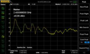
Performing a bandwidth test will help to determine if a pair of matched antennas will operate properly at the desired frequency bandwidth. This test must be performed on a spectrum analyser that can operate at the desired frequency bandwidth and has a tracking generator built in; this allows the user to inspect the operating bandwidth as a function of its own power level. This is done by connecting the antenna to the front of a spectrum analyser that has the tracking generator enabled. When the test is performed the spectrum analyser, will transmit a sine wave that is being swept across the desired frequency bandwidth while listening for the signal with the input of the spectrum analyser, and then compare the power level of the transmitted signal. To perform this, test the entire range of the spectrum analyser was used from 9kHz to 7.5GHz to determine the best operating bandwidth for the antennas. See Figure 1.

Figure 1: A bandwidth test being performed on two matched antennas that are rated for the 2.4GHz bandwidth.
As shown in Figure 1, the frequency ranges where the antenna received the most power at 900MHz bandwidth, 1.5GHz bandwidth and at 2.4GHz bandwidth: therefor this antenna is capable of being used efficiently at these three bandwidths. This makes this antenna and excellent choice for either Wi-Fi or Bluetooth applications which operate at 2.4 GHz bandwidth.
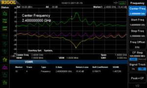
The next test requires the use of a spectrum analyser with a tracking generator as well as a VSWR bridge. The VSWR test is designed to determine the reflection coefficient of a given antenna to help determine the most efficient antenna at a given frequency. VSWR is determined by measuring the voltage standing waves along a transmission line leading to an antenna, it is the ratio of the peak amplitude of a standing wave and the minimum amplitude of a standing wave. When an antenna’s impedance is not matched with the transmission line, power is reflected reducing the amount of transmitted power. The ideal VSWR would be equal to 1 (no power being reflected) at the desired frequency. To perform this, test the desired frequency (2.4GHz) was selected and then the antenna was attached the bridge. A VSWR bridge measures the amount of power that is transmitted into antenna and compares it with the reflect power. Due to the design of a VSWR bridge most of the power that is reflected at a given frequency is the reflected power from the antenna. See Figure 2.

Figure 2: The image shows a VSWR test being performed on an antenna that is meant to operate at 2.4 GHz and has a VSWR of 1.17.
Based on Figure 2, the antenna has a VSWR of 1.17 at a frequency of 2.4GHz which makes this antenna almost an ideal antenna for Wi-Fi and Bluetooth communication. With a more efficient antenna, less power is required for transmission, which can increase the effective range of the device. Focusing on improving this one aspect of the IoT device can vastly improve the functionality of the device and address a number of challenges inherent in the overall design.
Additional Areas of Interest
Range is another critical aspect of an IoT device’s design. Sufficient range is required to facilitate wireless communication between IoT devices or with the internet. It is a critical aspect of the initial design and protocol selecting process. For instance, Near-Field Communication (NFC) is a communication technique that is used to transmit information over a couple of inches whereas Bluetooth is used to transmit information for tens of feet. Range requirements will also affect what type of antenna is being used to transmit data, along with determine whether to use a highly directional antenna or an omni directional antenna. Another consideration is the effective range required will determine the amount of power that is needed for transmission; thus, an antenna that makes more efficient use of the available power will help to ensure that the device will have the desired range.
Another area of interest to improve the functionality of an IoT device by eliminating or reducing interference to the RF signal. Interference can be generated by the electronic components used in the device itself such as the PCB, battery or user interface, or it can also be generated by the enclosure used to both protect the electronic components and improve the appearance of the device.
Conclusion and Key Learnings
With more Internet of Things devices being conceptualized every day, creating reliable Radio Frequency communication is an essential step towards creating a device that will stand out among the crowd. Successful device manufacturers must overcome the most difficult efficient antenna possible. Key test and measurement equipment will help facilitate basic antenna testing and interference testing that will help overcome these RF communication challenges.


 FREE SHIPPING £75+
 CELEBRATING 50+ YEARS
 PRICE MATCH GUARANTEE


