 FREE SHIPPING £75+
 CELEBRATING 50+ YEARS
 PRICE MATCH GUARANTEE


Description
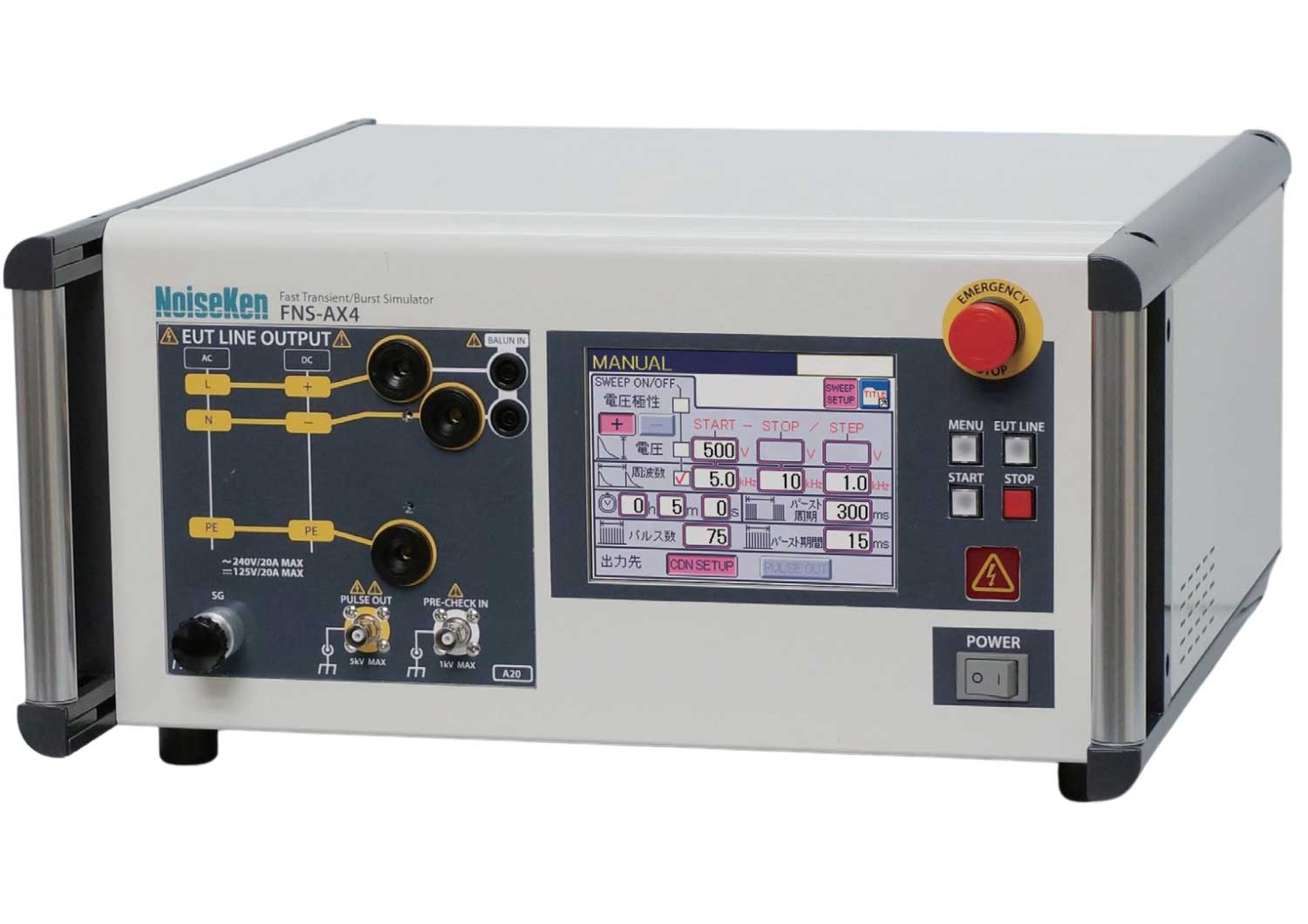
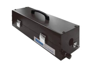
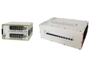
NoiseKen FNS-AX4-A20 Fast Transient Burst Simulator IEC 61000-4-4 Ed.3
The FNS-AX4 Series represents Noise Laboratory’s latest generation of Fast Transient/Burst (EFT/B) simulators, designed for IEC 61000-4-4 Ed 3 compliance testing — the 3.0 edition of the standard.
These instruments feature built-in Coupling/Decoupling Networks (CDN) and support both common mode and optional normal mode tests (per ANSI C37.90.1) to ensure comprehensive immunity evaluation for AC and DC power lines.
Their touchscreen operation, multi-language interface, and PC/Android remote-control software make them intuitive, efficient, and ready for modern EMC laboratories.
Key Features
- Fully compliant with IEC 61000-4-4 Edition 3.0 — designed for full calibration of the latest 3.0 standard.
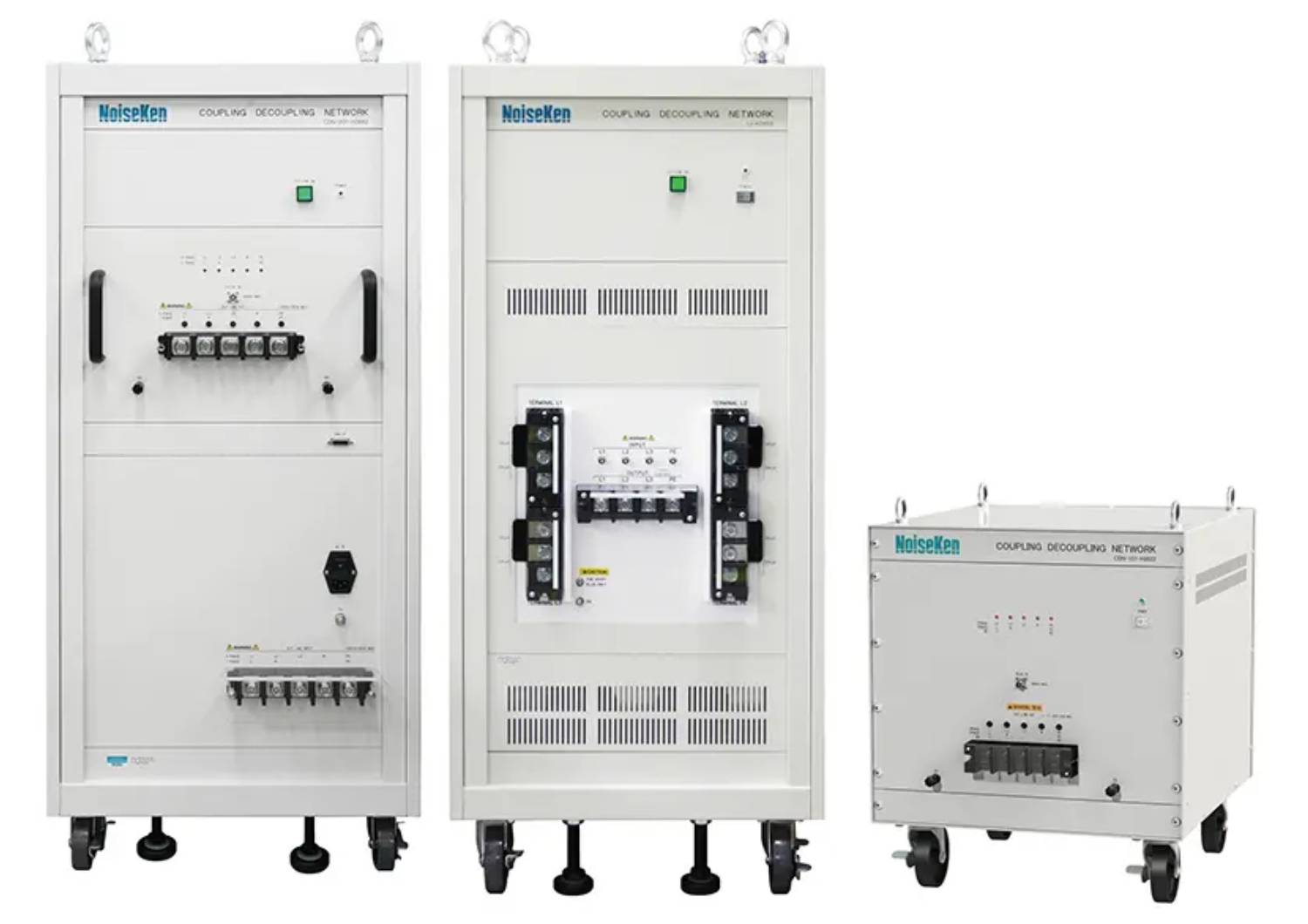
- Built-in CDN (Coupling/Decoupling Network) — selectable coupling phases for all power configurations.
- User-friendly LCD touchscreen with intuitive menus and numeric keypad for simple operation.
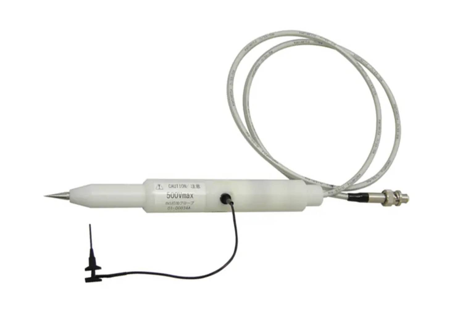
- Pre-check function — built-in waveform monitor eliminates need for external attenuator or oscilloscope during setup.
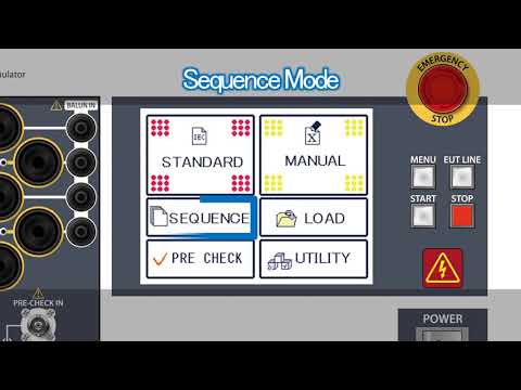
- Three test modes: Standard (preset per IEC), Manual (custom setup and sweep), and Sequence (automated multi-step execution).
- Remote control and data logging available via Windows and Android™ software options.
- Automatic test logging with calibration date reminders.
- Multi-language interface — English, Japanese, Chinese, and Korean supported.
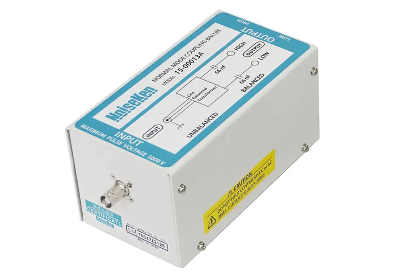
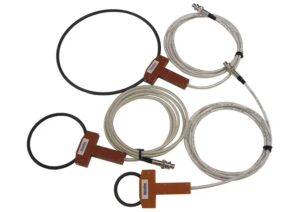
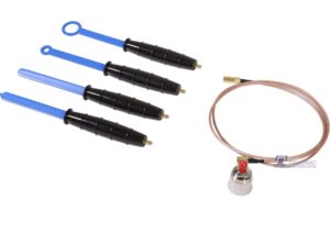
- Optional Normal Mode Test (ANSI C37.90.1) with dedicated coupling balun (Model 15-00013A).
- Comprehensive safety system including emergency stop, 3-channel EUT FAIL input, and indicator outputs.
| Item | FNS-AX4-A20 | FNS-AX4-B63 |
|---|---|---|
| Power capacity (EUT) | AC 240 V / 20 A • DC 125 V / 20 A (PE 10 A) | AC 600 V / 63 A • DC 125 V / 63 A (N/PE 10 A) |
| Coupling phases | L / N / PE | L1 / L2 / L3 / N / PE |
| Waveform (50 Ω load) | Peak = (Set V)/2 ± 10 % • Rise time 5.5 ns ± 1.5 ns • Width 45 ns ± 15 ns | |
| Pulse frequency range | 5 kHz – 100 kHz | |
| Maximum test voltage | ± 4 kV (EFT/B compliant waveform) | |
| Residual voltage | < 10 % of set voltage | |
| Sync phase angle | 0 – 360 ° (1 ° steps) ± 10 % | |
| Environment | 15 – 35 °C / 25 – 75 % RH | |
| Dimensions (W×H×D) | 430 × 222 × 437 mm (≈ 14 kg) | 430 × 222 × 437 mm (≈ 22 kg) |
| Power supply | AC 100 – 240 V ± 10 %, 50/60 Hz ≈ 120 VA | |
What's Included
- FNS-AX4-A20 main unit
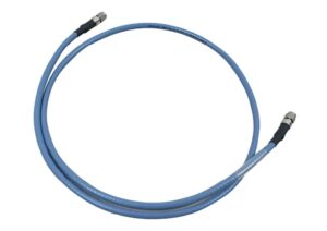
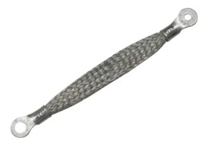
- SG cable (0.1 m, Model 05-00103A)
- AC power cord
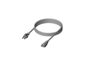
- Line input cables – A20 type (3 pcs) / B63 type (5 pcs, Model 05-00151A or 05-00152A)
- Line output cables – A20 type (3 pcs) / B63 type (5 pcs, Model 05-00157A)
- CDN waveform verification connector (Model 02-00152A)
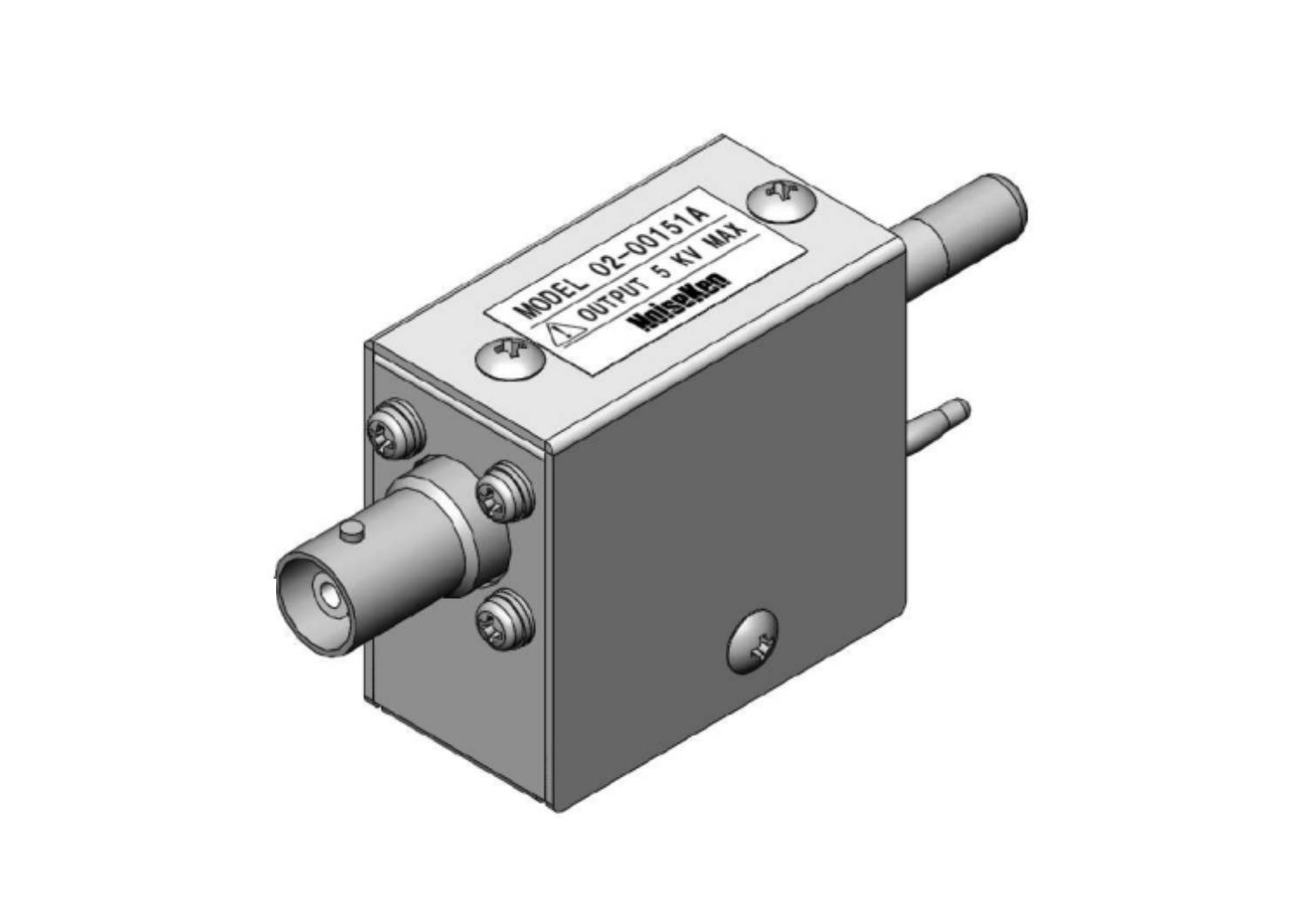
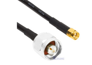
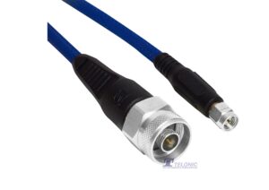
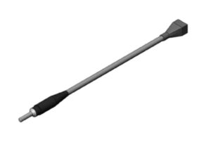
- Coaxial cable for pre-check (0.3 m, Model 02-00151A)
- Accessory bag
- Instruction manual (common for A20/B63)
Compliance Standards
- IEC 61000-4-4 Edition 3.0 — full compliance and calibration alignment with the latest standard.
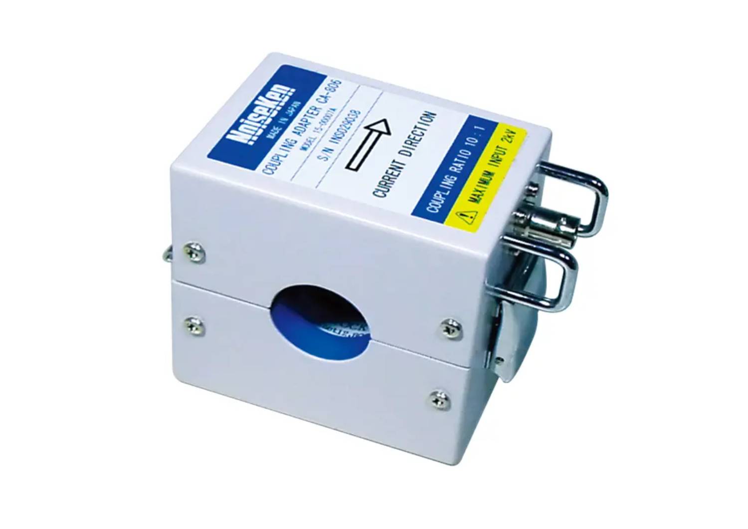
- ANSI C37.90.1 Normal-Mode Test — supported with optional Normal-Mode Coupling Balun (Model 15-00013A).
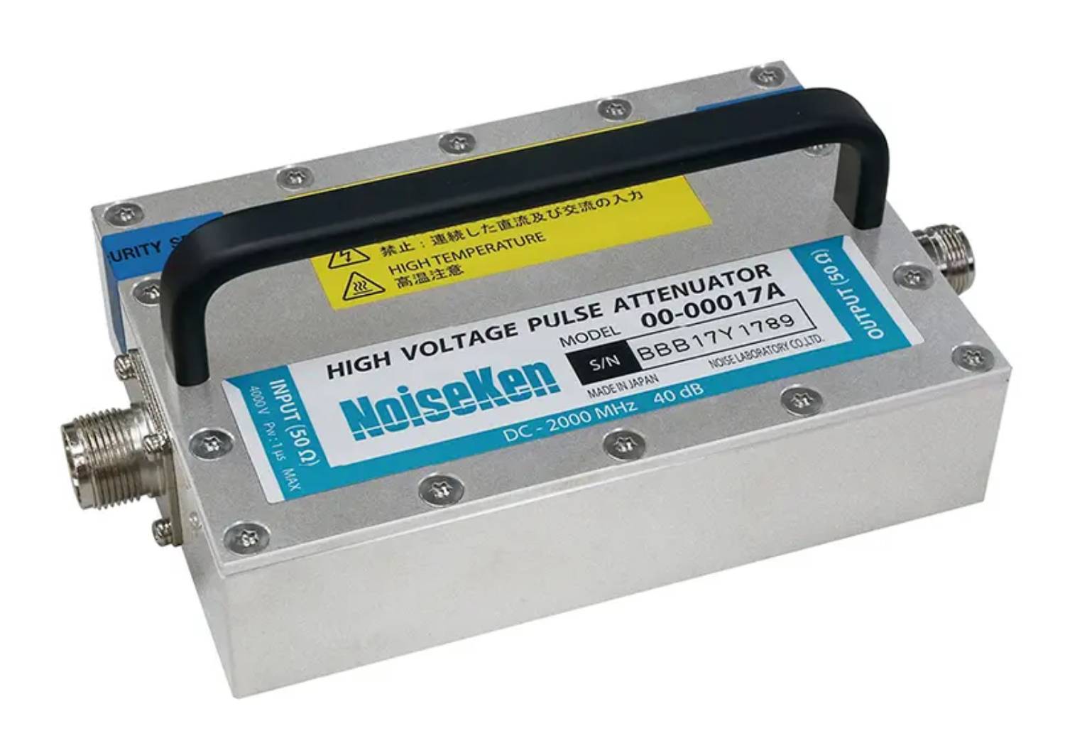
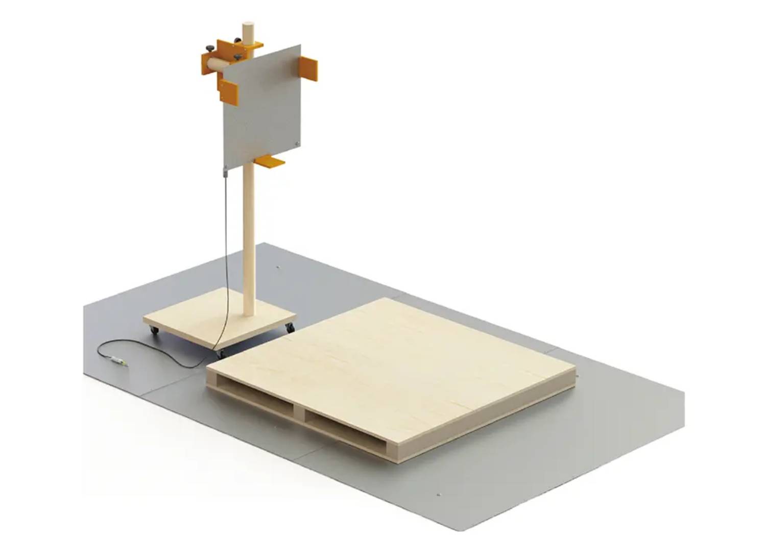
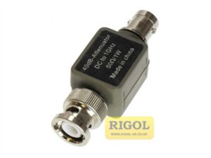
- Waveform verification per IEC 61000-4-4 using optional attenuators (Model 00-00017A 50 Ω / 00-00018A 1 kΩ).
Applications
- EMC compliance and calibration laboratories conducting IEC 61000-4-4 Edition 3 testing.
- Product development and pre-compliance verification for consumer, automotive, industrial, and medical electronics.
- Evaluation of fast transient/burst immunity on AC or DC power lines.
- A20 model: ideal for single-phase tabletop or small EUT testing.
- B63 model: designed for high-capacity three-phase or industrial EUT applications.
Product Images

Easy to perform pre-test inspection with pre-check function

Coupling Balun available for normal mode test

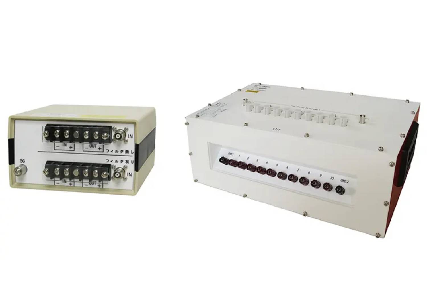
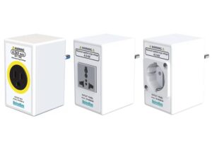
Simple and Easy EUT power line connection
×
![]()


 FNS-AX4 Catalogue


Reviews
There are no reviews yet.