Description
Advanced Measurement Kit for the SVA1000X Series Spectrum Analyser.
Advanced Measurement Kit(Opt.) CHP, ACPR, OBW, CNR, Harmonic, TOI, Monitor
Summary of advanced broadcast/transmission
measurements provided with the SSA/SVA option
December 06, 2018
The SSA and SVA products feature optional advanced measurements that are ideal for broadcast and
transmission measurement applications.
Here is a summary of the measurements included in the Advanced Measurement Kit (AMK) option:
NOTE: More details can be found in the analyzer Users Guides
Channel Power
Measure the power and power density within the specified channel bandwidth. When this function is
enabled, the span and resolution bandwidth are automatically adjusted to smaller values. Select Channel
Power and press Meas Setup to set the corresponding parameters.
Measurement Results: Channel power and power spectral density.
Channel Power: Power within the integration bandwidth.
Power Spectral Density: Power (in dBm/Hz) normalized to 1 Hz within the integration bandwidth.
Measurement Parameters: Center Freq, integration bandwidth, Span, Span power.
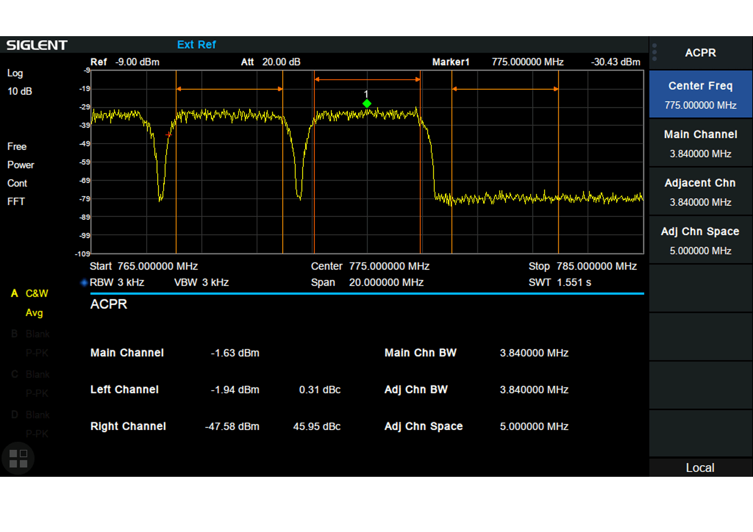
ACPR
Measure the power of the main channel and adjacent channels as well as the power difference between
the main channel and each of the adjacent channels. When this function is enabled, the
span and resolution bandwidth of the analyzer are adjusted to smaller values automatically. Select ACPR
and press Meas Setup to set the corresponding parameters
Adjacent Channel Power Measurement: Main CH Power, Left channel power and Right channel
power.
Main CH Power: Displays the power within the bandwidth of the main power
Left channel power: Display the power of channel to the left of the main channel and the power
difference between the left channel and the main channel (in dBc)
Right channel power: Display the power of the channel to the right of the main channel and the
power difference between the right channel and the main channel (in dBc)
Measurement parameters: Center frequency, main channel bandwidth, adjacent channel
bandwidth and channel spacing
Occupied BW
Integrate the power within the whole span and calculate the bandwidth occupied by this power
according to the specified power ratio. The OBW function also indicates the difference (namely
“Transmit Freq Error”) between the center frequency of the channel under measurement and the
center frequency of the analyzer. Select Occupied BW and press Meas Setup to set the
corresponding parameters.
OBW measurement: Occupied bandwidth and transmit frequency error.
Occupied Bandwidth: Integrate the power within the whole span and then calculate the
bandwidth occupied by the power according to the specified power ratio.
Transmit Frequency Error: The difference between the center frequency of the channel and the
center frequency of the analyzer.
T-Power
The system enters zero span mode and calculates the power within the time domain. The types of powers
available including: Peak, Average and RMS. Select T-Power and press Meas Setup to set the
corresponding parameters.
T-Power: The power of the signal from the start line to the stop line.
Measurement Parameter: Center frequency, start line, stop line.
TOI
Automatic measurement of IP3 (Third-order Intercept Point), including the power of the fundamental wave
and the Third order in the power domain. Calculate the adjustable Intercept Point
Spectrum Monitor
Display the power of scanned spectra using color grading as well as collect a “waterfall” chart showing
successive scans with respect to time. Select Spectrum Monitor and press Meas Setup to set the
corresponding parameters.






 FREE SHIPPING £75+
 CELEBRATING 50+ YEARS
 PRICE MATCH GUARANTEE


Reviews
There are no reviews yet.