 FREE SHIPPING £75+
 CELEBRATING 50+ YEARS
 PRICE MATCH GUARANTEE
Description
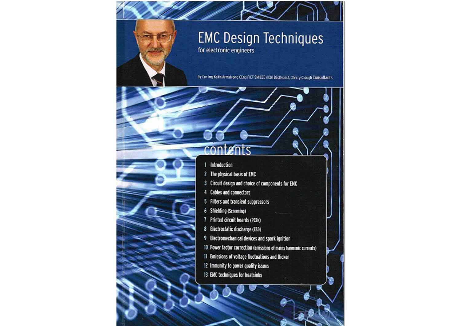
EMC Design Techniques for electronic engineers by Keith Armstrong BSc(Hons) CEng FIET SMIEEE ACGI.
Contents: Introduction, The physical basis of EMC, Circuit design and choice of components for EMC, Cables and connectors, Filters and transient suppressors, Shiedling (screening), Printed circuit boards (PCBs), Electrostatic discharge (ESD), Electromechanical devices and spark ignition, power factor correction (emissions of mains harmonic currents, Emissions of voltage fluctuations and flicker, Immunity to power quality issues, EMC techniques for heatsinks.


Reviews
There are no reviews yet.