 FREE SHIPPING £75+
 CELEBRATING 50+ YEARS
 PRICE MATCH GUARANTEE


PCR-LE/LE2 Series feature the Surge Suppression function that involves the process of protecting PCR-LE/LE2 from voltage spike.
You can choose Surge Suppression to turn on or off depending on your load condition. If you want to avoid any voltage overshooting or undershooting, always set Surge Suppression to on. However, when you use a load with regenerative feedback (e.g. capacitive load or battery), it is recommended that Surge Suppression is set to off. In this white paper, we are going to provide the details of Surge Suppression function and make clear the difference between when Surge Suppression is set to on and off.
1. Surge Suppression: On
Surge Suppression is set to on as factory default.
1-1. Timing Chart
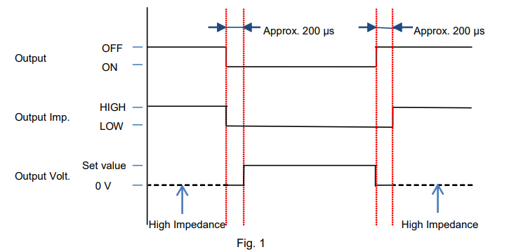
Figure 1 shows the timing chart when Surge Suppression is on;
1. The output is in the high impedance state while the output is turned off.
2. When the output is turned on, the voltage stays at 0 V for first 200 microseconds, and then the voltage rises to the set value.
3. When turning off the output, the voltage firstly falls to 0 V for approx. 200 microseconds, and then the output stays in the high impedance state.
Thanks to this ‘staying at 0 V for approx. 200 microseconds’ behaviour, Surge Suppression can prevent the voltage overshooting or undershooting when the output is turned off. Even if an inductive kickback (reverse voltage surge) occurs due to an inductive load, PCR-LE/LE2 can absorb a reverse current during these 200 microseconds.
The reverse current means a discharging current for the inductive load. If the discharging current may affect your load state, set Surge Suppression to off.
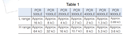
For your reference, Table 1 shows the high impedance value.
1-2. Voltage Waveforms
The following figures are the actual voltage waveforms when the output was turned off with different loads. Conditions: Output 50 Vdc by PCR500LE and turn it off.
No-load state: See Figure 2. The voltage kept at 0 V for approx. 200 microseconds. The undershooting was seen soon after the output shifted to the high-impedance state.
With the lower load resistance (See Figure 3 and 4) or large capacitor (See Figure 5), the undershooting was reduced or almost eliminated.
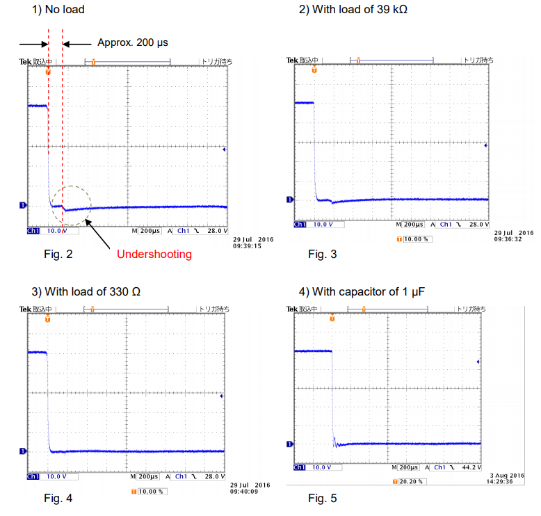
The undershooting was caused by 1) a switching circuit in PCR500LE that switches from low to high impedance 2) capacitors (X-capacitor and Y-capacitor) at PCR500LE’s output terminal and 3) internal wirings in PCR500LE.
Quite small energy was stored into the internal wirings in PCR500LE when the output was turned off. This residual energy was dissipated in the load resistance or capacitance. Thus, the voltage undershooting was suppressed, as shown in Figures 3 through 5.
2. Surge Suppression: Off
You can set Surge Suppression to off;
If you do not want to let the reverse current flow back to PCR-LE/LE2 when the output is turned off, or
If you simulate the event like; While PCR-LE/LE2 provides a DC output to an inductive load, its load cable is suddenly disconnected.
For the instruction how to set Surge Suppression to off, see Appendix in Section 4.
2-1. Timing Chart
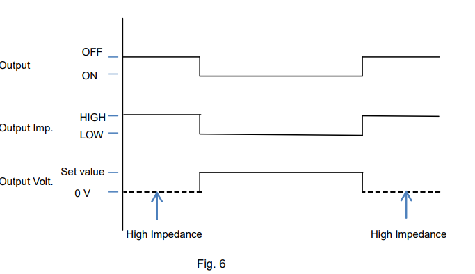
The timing chart in Figure 6 shows that;
1. The output is in the high impedance state while the output is turned off.
2. When the output is turned on, the output shits to the low impedance state and the voltage rises to the set value.
3. When turning off the output, the output shifts to the high impedance state.
With Surge Suppression turned off, the followings may happen;
The rising voltage becomes unstable.
The voltage overshooting is seen on the rising voltage.
The rising voltage is fluctuated by the load state.
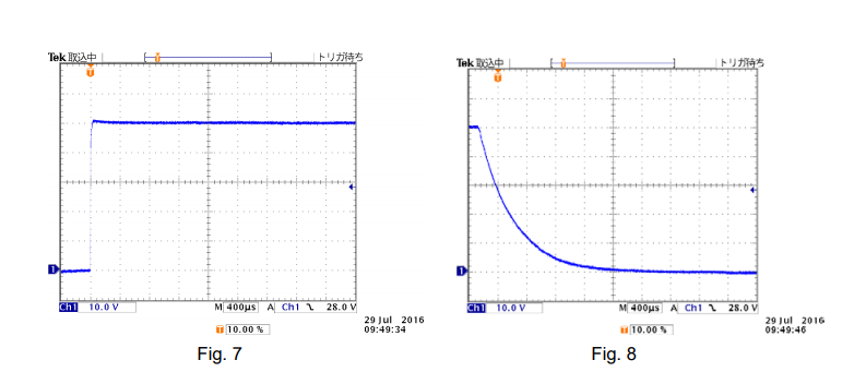
2-2. Voltage Waveforms
See the figures below for the measurement voltage waveforms when the output was turned on and off under the following conditions; Output 50 Vdc by PCR500LE and turn it off in no-load state.
In Figure 7, the rising voltage was somewhat unstable.
In Figure 8, when the output was turned off, the residual energy in PCR500LE was gradually released with high impedance, and accordingly the voltage fell down slowly.
3. Recommendations
Surge Suppression is necessary and useful function; however it cannot provide its optimum performance with the wrong setting. We recommend that you choose whether to turn Surge Suppression on or off depending on the characteristics of your DUT.
Surge Suppression is available with the firmware Ver. 4.50 or later.
If you installed the firmware Ver. 4.50 or earlier, the output on/off operation is fixed as Surge Suppression is set to on, that is, you cannot turn Surge Suppression off.
To update your firmware, visit the following website:
https://www.kikusui.co.jp/en/download/en/?fn=pcr-le_FW
* Also please read the supplementary paper of ‘Voltage Interruption Waveforms Provided by PCR-LE Series’.