In a test system, AC power supply is one of the significant components that can create test sequences for output and supply source to DUT. However, the power supply may cause a noise issue during test. There is some noise interference such as conducted noise and magnetic field that may enter into the test system.
This article focuses on a noise terminal voltage at an input and output terminal which is regarded as conducted noise and introduces how to reduce it. The procedures below are also effective for DC power supplies.
*In the following examples, the measured noise is below 150 kHz.
1. Type of Power Supply Noise
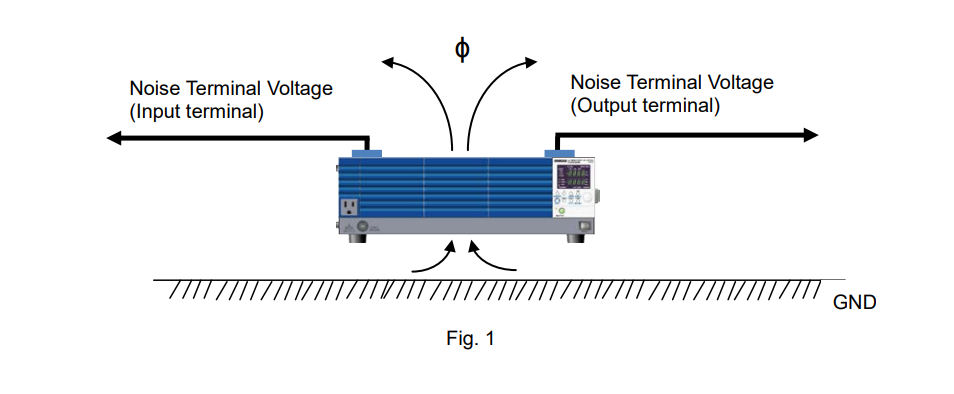
As shown in Figure 1, the power supply noise is mainly classified into the noise terminal voltage (at the input and output terminal) and emission noise. The emission noise is emitted as the magnetic field and measured as the noise voltage.
2. Noise Terminal Voltage at Input Terminal
2-1 Measurement Circuit Configuration
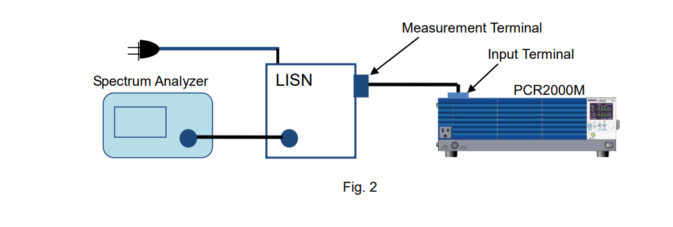
Figure 2 shows that the input terminal of PCR2000M is connected to the Line Impedance Stabilization Network (LISN) to measure the noise terminal voltage.
2-2 Method and Result
Connect the input N terminal to the GND terminal (See Figure 4 for the result). If the system has a leakage current breaker, it may shut down. To avoid this, add a capacitor between the N terminal and GND terminal to flow the leakage current.

3. Noise Terminal Voltage at Output Terminal
3-1 Measurement Circuit Configuration
Figure 5 shows that the output terminal of PCR2000M is connected to the LISN to measure the noise terminal voltage.

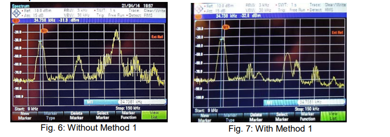
3-2 Method 1 and Result
Method 1: Connect the output N terminal to the GND terminal. If you cannot directly connect them, add a capacitor between the N terminal and the GND terminal.
3-3 Method 2 and Result
Method 2:
1) Add an inductance* to the output L terminal.
2) Connect the output N terminal to the GND terminal. (*Wind 6 turns on a toroidal core.)

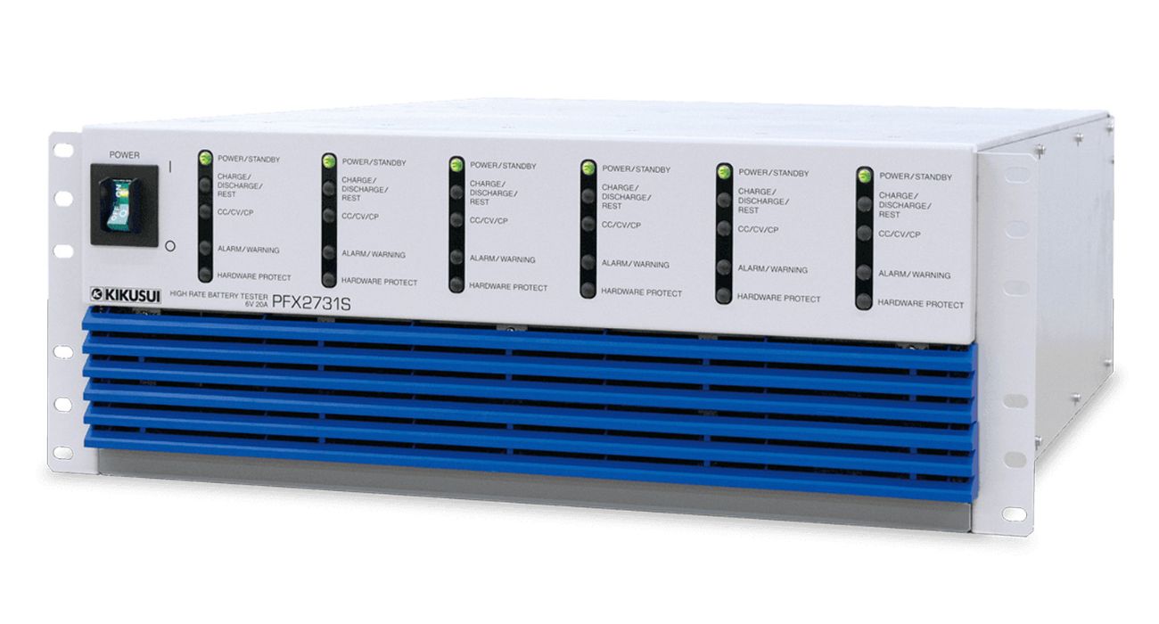
Products Mentioned In This Article:
- Kikusui AC Power Supplies please see HERE






 FREE SHIPPING £75+
 CELEBRATING 50+ YEARS
 PRICE MATCH GUARANTEE


