 FREE SHIPPING £75+
 CELEBRATING 50+ YEARS
 PRICE MATCH GUARANTEE


RF current probes are useful for measuring common-mode current on cables without disconnecting the conductor. When the probe’s frequency-dependent transfer impedance is entered into EMCview as a correction, a spectrum analyser voltage reading can be displayed as current in dBµA.
Transfer impedance and transducer factor
A current probe produces an output voltage in response to current through the conductor. Its transfer impedance is defined as ZT = V / I and is normally specified in ohms or dBΩ versus frequency.
When voltage is expressed in dBµV and transfer impedance in dBΩ, the current is calculated as:
Current in dBµA = measured voltage in dBµV – transfer impedance in dBΩ
Some manufacturers publish a transducer factor in dB(1/Ω) instead. This is the negative of transfer impedance expressed in dBΩ, so it is added to the measured voltage:
Current in dBµA = measured voltage in dBµV + transducer factor in dB(1/Ω)
Worked example
Assume the analyser measures 40 dBµV at a frequency where the probe transfer impedance is 10 dBΩ. The corresponding current is 40 – 10 = 30 dBµA. If the probe data instead gives a transducer factor of -10 dB(1/Ω), the same result is obtained by calculating 40 + (-10) = 30 dBµA.
Create the EMCview correction data
- Obtain the probe’s calibrated transfer-impedance or transducer-factor data across the frequency range.
- Use enough frequency points to represent changes in the probe response; do not assume one value across the full band.
- If the source is transfer impedance in dBΩ, invert its sign to create an additive transducer-factor correction.
- Enter frequency and correction pairs into the EMCview correction file using the format expected by the software.
- Check the result at several frequencies with a known or independently calculated value before relying on the full sweep.
Measurement precautions
- Keep the conductor in a repeatable position within the probe aperture.
- Observe the probe’s current, voltage, frequency and safety limits.
- Characterise or account for any preamplifier and cable used between the probe and analyser.
- Check the analyser for overload when large low-frequency or switching components are present.
- Record whether displayed values are voltage, current, transfer impedance or transducer factor; the units are not interchangeable.
STACKABLE: RF current probes and EMCview
-
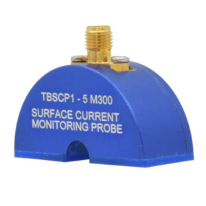
TEKBOX TBSCP1-5M300 30 kHz to 400 MHz RF Current Monitoring Probe
£410.00 (£492.00 inc. VAT)Available on back-order
Availability: Stock models delivered next working day (UK only) for orders placed before 16:30 (Mon - Fri)
Add to basket
-
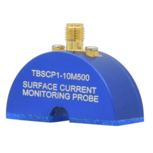
TEKBOX TBSCP1-10M500 9 kHz to 600 MHz RF Current Monitoring Probe
£480.00 (£576.00 inc. VAT)Available on back-order
Availability: Stock models delivered next working day (UK only) for orders placed before 16:30 (Mon - Fri)
Add to basket
-
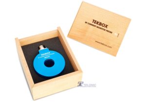
TEKBOX TBCP1-500 30kHz to 500MHz RF Current Monitoring Probe
£372.00 (£446.40 inc. VAT)1 in stock (can be backordered)
Availability: Stock models delivered next working day (UK only) for orders placed before 16:30 (Mon - Fri)
Add to basket
-
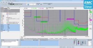
TEKBOX EMCview Pro PC Software Licence
£653.00 (£783.60 inc. VAT)Available on back-order
Availability: Stock models delivered next working day (UK only) for orders placed before 16:30 (Mon - Fri)
Add to basket
This article is based on the Tekbox procedure for incorporating RF current-probe correction data into EMCview. Use the calibration data supplied with the specific probe wherever available.