 FREE SHIPPING £75+
 CELEBRATING 50+ YEARS
 PRICE MATCH GUARANTEE


MIL-STD-461 CS109 evaluates whether equipment remains functional when low-frequency current flows through its conductive enclosure or structure. The Tekbox TBMR-110M turns the measurement into a controlled sweep, using either a conventional amplifier-and-transformer path or direct current injection with the TBRFCI1.
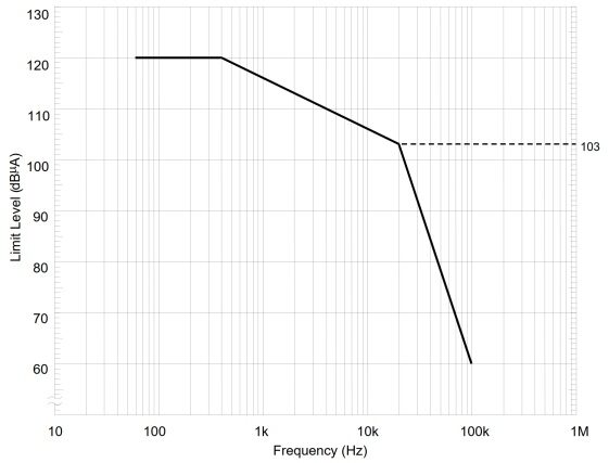
The source application note covers 60 Hz to 100 kHz and a maximum test current of 120 dBµA, equivalent to 1 A RMS. The required limit and applicability must always come from the contractual standard edition and the approved test plan.
Engineering note: this article explains the workflow shown in the Tekbox application note. It does not replace MIL-STD-461, the equipment test plan, laboratory safety controls or the grounding and isolation requirements for the EUT and test equipment.
What CS109 is designed to reveal
Current flowing through a chassis can create small voltage differences across joints, shields and reference points. Sensitive low-frequency circuits may then respond to the resulting magnetic fields or common-impedance coupling. CS109 reproduces that condition in a controlled way so susceptibility can be identified before it becomes a system-level problem.
The source note summarises the method as applying to equipment and subsystems operating at 100 kHz or less with sensitivity of 1 µV or better, while identifying handheld equipment as exempt. Treat that as a guide to the note: applicability must be checked against the edition invoked by the programme.
The conventional transformer-coupled arrangement
The standard arrangement drives the EUT structure through a power amplifier, coupling transformer and 0.5 Ω load resistor. A current probe measures the actual injected current and returns it to the receiver. The EUT and test hardware share a carefully controlled single-point ground connection.
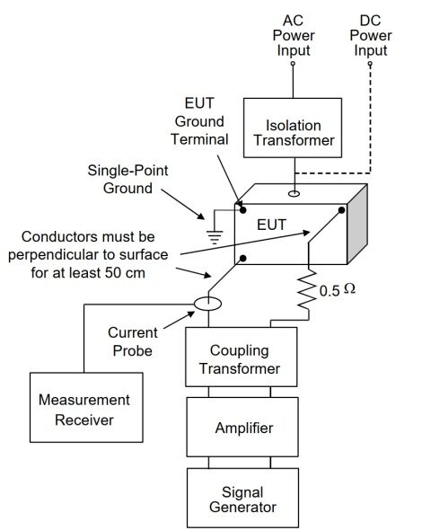
The current Tekbox TBJT04 uses a 2:1 turns ratio, producing the 4:1 impedance transformation required by this application. The distinction matters: the “4:1” figure describes impedance ratio rather than turns ratio.
Automating CS109 with the TBMR-110M
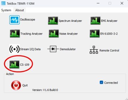
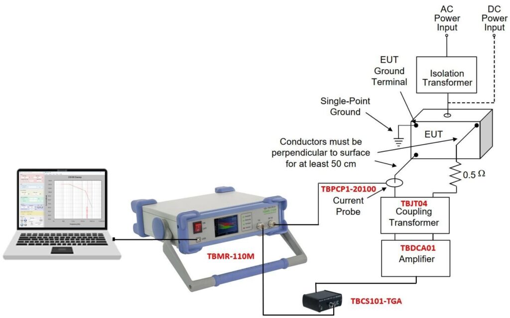
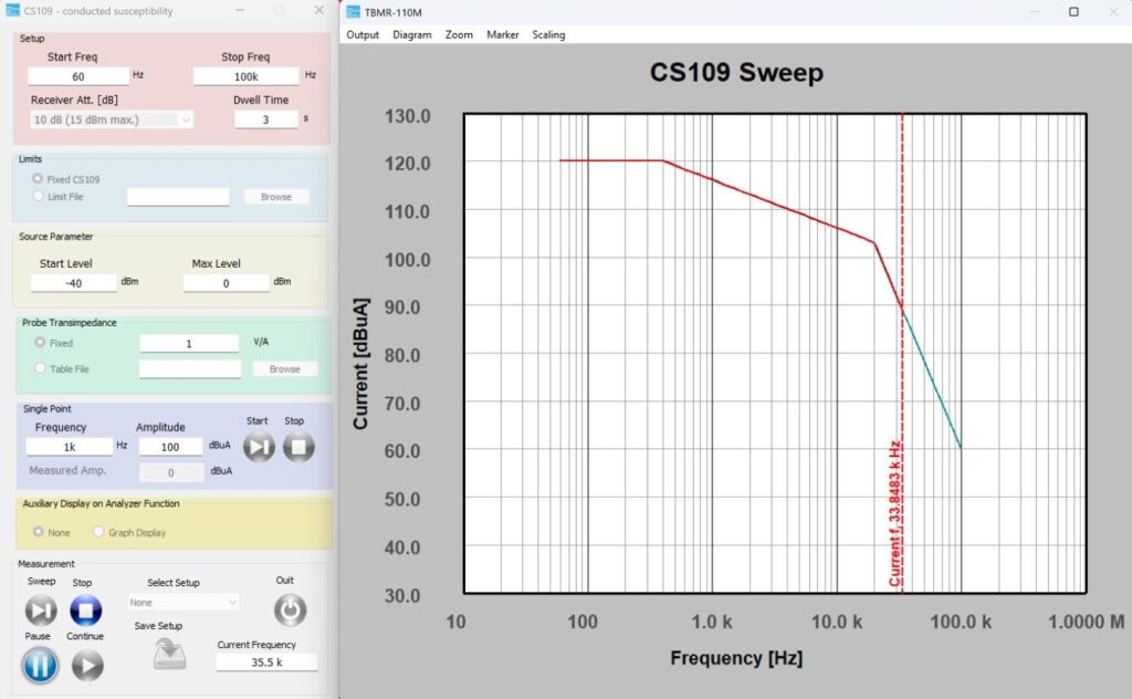
The TBMR-110M combines a low-frequency EMI receiver with a tracking generator. Its PC software includes a dedicated CS109 application, allowing the same instrument to create the swept drive signal, measure the current feedback and regulate the output at each frequency point.
TBMR-110M
Supplies the sweep through its tracking generator, measures the returned current signal and runs the closed-loop application.
TBCS101-TGA
An optional DC-coupled 20 dB driver amplifier for installations that need more tracking-generator level ahead of the main power amplifier.
TBDCA1 and TBJT04
The DC-coupled power amplifier produces the required current; the transformer couples that energy into the low-impedance test path.
TBR-CS101 and TBPCP1-20100
The 0.5 Ω resistor completes the defined path while the current probe supplies the feedback measurement used for levelling.
Alternative direct injection with the TBRFCI1
The TBRFCI1 is a four-quadrant current injector that can drive the structure directly, up to the 1 A RMS maximum described in the note. Its current-monitor output provides the feedback signal, removing the separate coupling transformer, load resistor and current probe from this version of the setup.
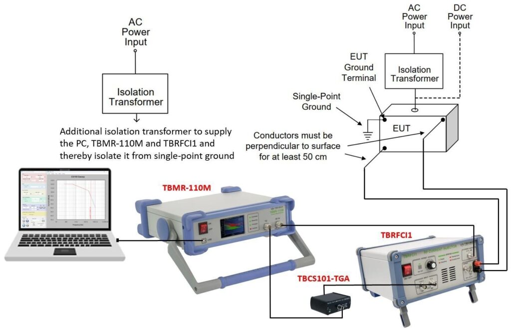
Because the injection path is tied to the EUT structure, the application note calls for an additional isolation transformer for the PC, TBMR-110M and TBRFCI1 supply arrangement. Grounding and isolation should be reviewed before energising either configuration.
Software setup: the values that matter
| Setting | Purpose | Practical check |
|---|---|---|
| Frequency range and step size | Defines the 60 Hz to 100 kHz sweep and the required frequency progression. | Confirm the range and steps against the invoked standard edition and test plan. |
| Limit profile | Sets the requested current at each frequency. | Use the approved fixed value or imported limit file; do not rely on an illustration. |
| Receiver attenuation, gain and maximum input | Protects the receiver while retaining useful measurement range. | The note uses 10 dB attenuation and a 15 dBm maximum-input setting as a suitable starting point for its setup. |
| Probe or monitor transimpedance | Converts the receiver reading into injected current. | Load the correction for the exact current probe, or enter the TBRFCI1 monitor response. |
| Dwell and stop conditions | Allows the EUT response to settle and makes failures observable. | Set these from the product test plan and the behaviour being monitored. |
Closed-loop levelling and the final trace
At each frequency, the software measures injected current and adjusts the tracking-generator drive until the selected limit is reached or an equipment limit intervenes. The result therefore shows the stress actually achieved, rather than assuming that a fixed source level produces the correct current across the complete sweep.
Working below the main tracking-generator range
The application note states that the TBMR tracking generator is accurate over a 50 dB range. Very low current levels can push the DDS attenuation beyond that main range. Its practical workaround is to pause the sweep at 70 dBµA, add a 10 dB attenuator at the tracking-generator output, then resume. The external attenuation moves the generator back into its more accurate operating region.
- The limit file, frequency steps, dwell time and software version.
- The complete equipment chain, serial numbers and correction data.
- The current actually achieved at every point and any levelling shortfall.
- The grounding, isolation and EUT operating configuration.
- Any frequency at which the EUT changes state, plus the monitored function and recovery behaviour.
- Any manual attenuation change or single-frequency investigation used to reproduce a failure.
The useful result is not simply that a sweep completed. It is a traceable record of the current that actually flowed through the structure, together with the EUT behaviour at each frequency.
Recommended products for the transformer-coupled setup
These are the current Telonic catalogue products corresponding to the principal items shown in the conventional arrangement.
-
Tekbox TBMR-110M EMI Test Receiver / Analyser DC-110 MHZ
£6,011.00 (£7,213.20 inc. VAT)Available on back-order
Availability: Stock models delivered next working day (UK only) for orders placed before 16:30 (Mon - Fri)
Add to basket -

TBPCP1-20100 RF pulse current monitoring probe
£820.00 (£984.00 inc. VAT)1 in stock (can be backordered)
Availability: Stock models delivered next working day (UK only) for orders placed before 16:30 (Mon - Fri)
Add to basket -

TEKBOX TBCS101-TGA DC – Coupled Low Noise Amplifier
£250.00 (£300.00 inc. VAT)2 in stock
Availability: Stock models delivered next working day (UK only) for orders placed before 16:30 (Mon - Fri)
Add to basket -
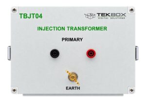
Tekbox TBJT04 injection transformer
.Available on back-order
Availability: Stock models delivered next working day (UK only) for orders placed before 16:30 (Mon - Fri)
Read more -
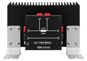
Tekbox TBR-CS101 0.5 Ohm Measuring Resistor
.Available on back-order
Availability: Stock models delivered next working day (UK only) for orders placed before 16:30 (Mon - Fri)
Read more -
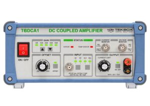
Tekbox TBDCA1 – DC to 10 MHz, 150 W DC-Coupled Power Amplifier
£4,050.00 (£4,860.00 inc. VAT)Available on back-order
Availability: Stock models delivered next working day (UK only) for orders placed before 16:30 (Mon - Fri)
Add to basket
Direct-current-injection alternative
The TBRFCI1 replaces the power-amplifier, transformer, resistor and separate current-probe path in the alternative arrangement.
-

Tekbox TBRFCI1 RF trans-conductance amplifier / current injector
£2,277.00 (£2,732.40 inc. VAT)Available on back-order
Availability: Stock models delivered next working day (UK only) for orders placed before 16:30 (Mon - Fri)
Add to basket
Source acknowledgement: method and figures adapted from the Tekbox application note “MIL-STD-461 CS109 Structure Currents”, version 1.0. Always use the applicable MIL-STD-461 edition, approved equipment test plan and equipment manuals as the authoritative requirements.