FREE SHIPPING £75+
 CELEBRATING 50+ YEARS
 PRICE MATCH GUARANTEE


Description
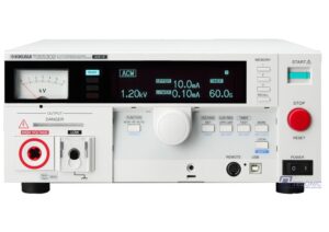
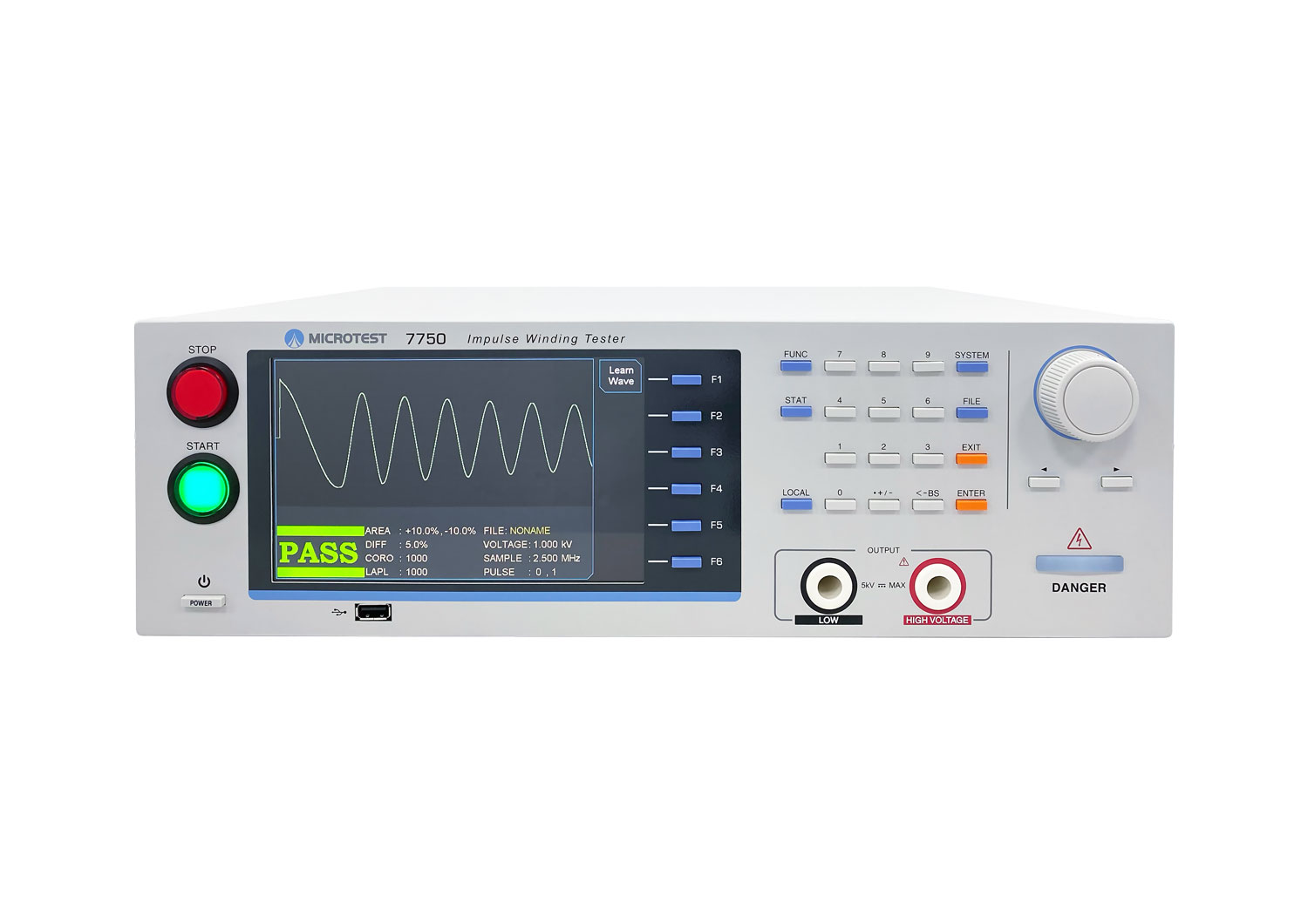
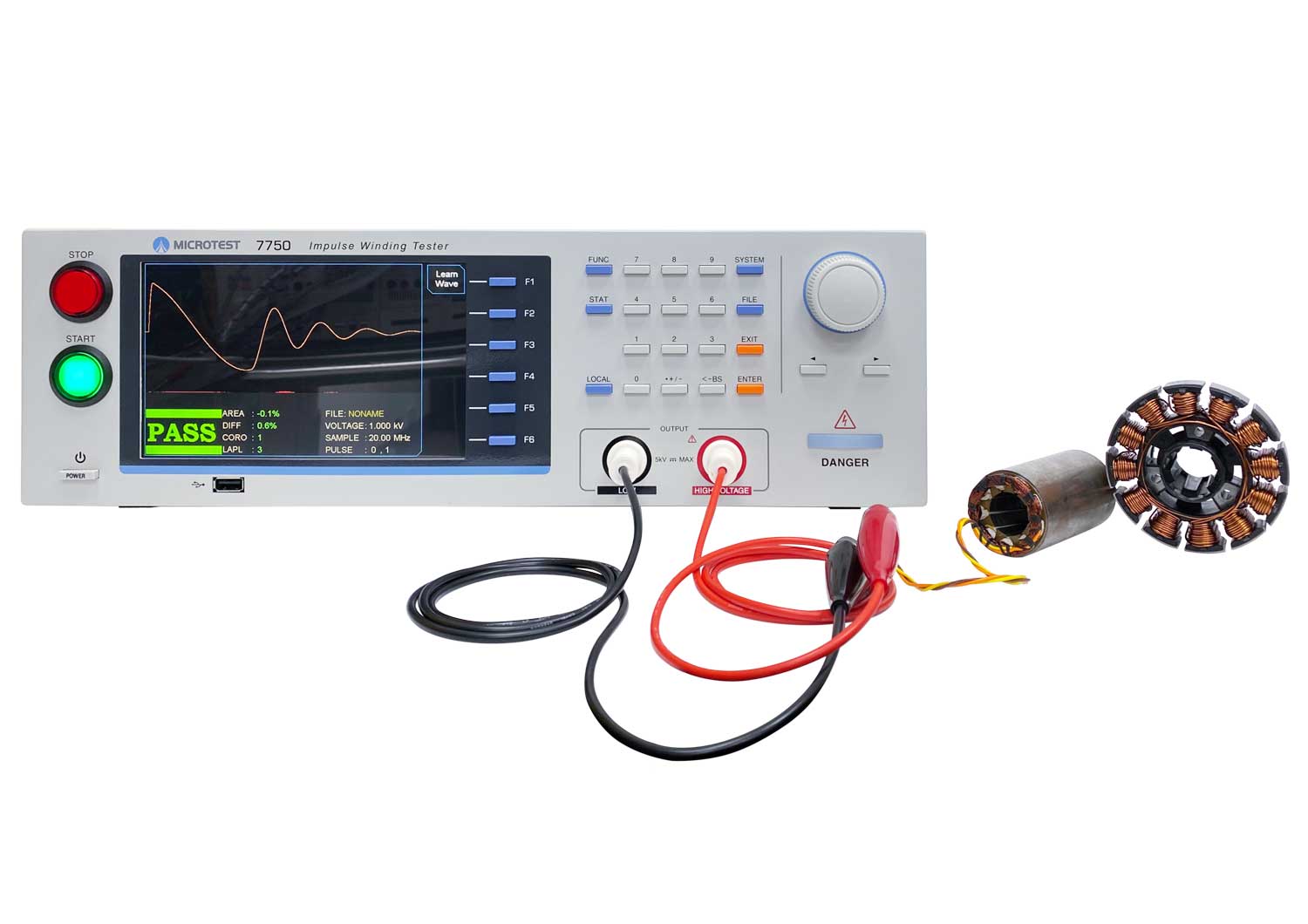
Microtest Impulse Winding Tester 7750-5S 100V~5200V
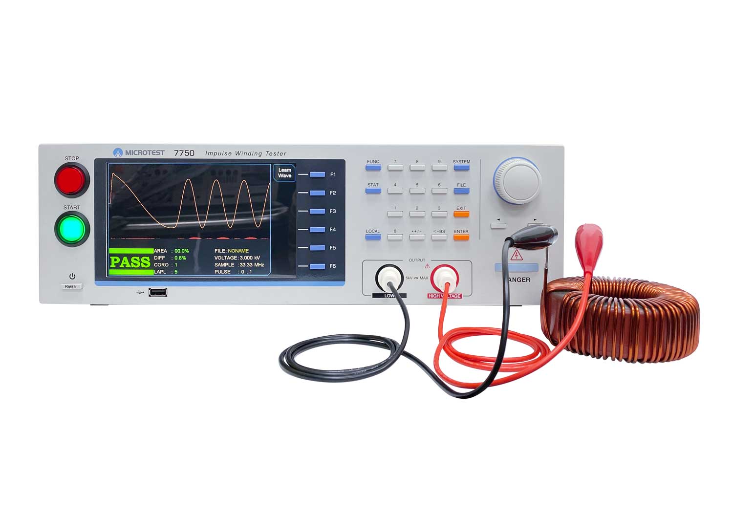
MICROTEST 7750-5S is a product in the 7550 Series. The 7750-5S is an advanced Impulse Winding Tester with a faster colour display screen. It provides pulse voltage outputs of 100V~5200V and utilizes high-speed sampling technology at 200MHz/9 bits. It offers various comparison modes such as total area, area difference, corona count, jitter count, second-order differentiation, and waveform comparison. With a testing speed of up to 10 times per second, it is ideal for high-speed production lines.
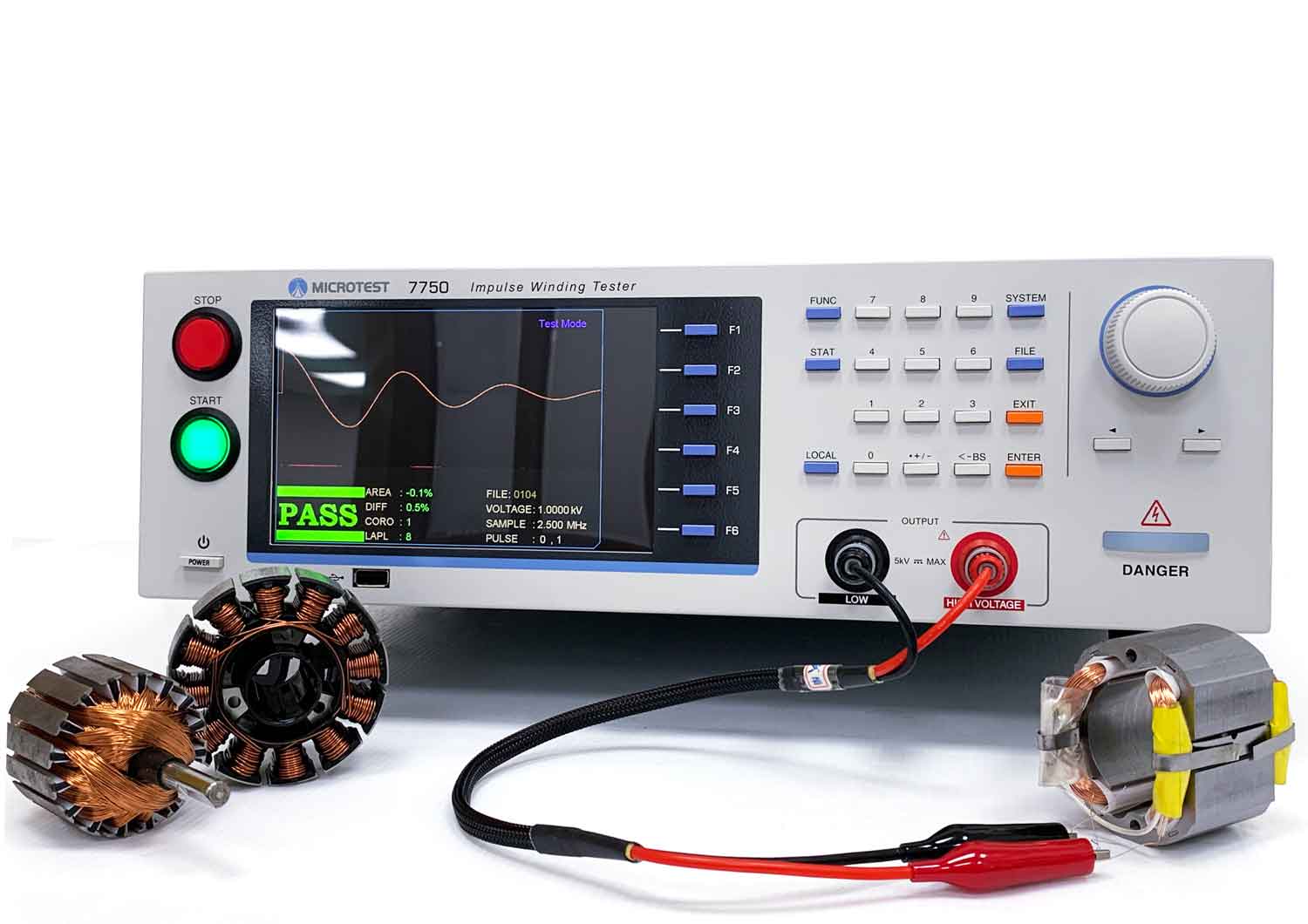
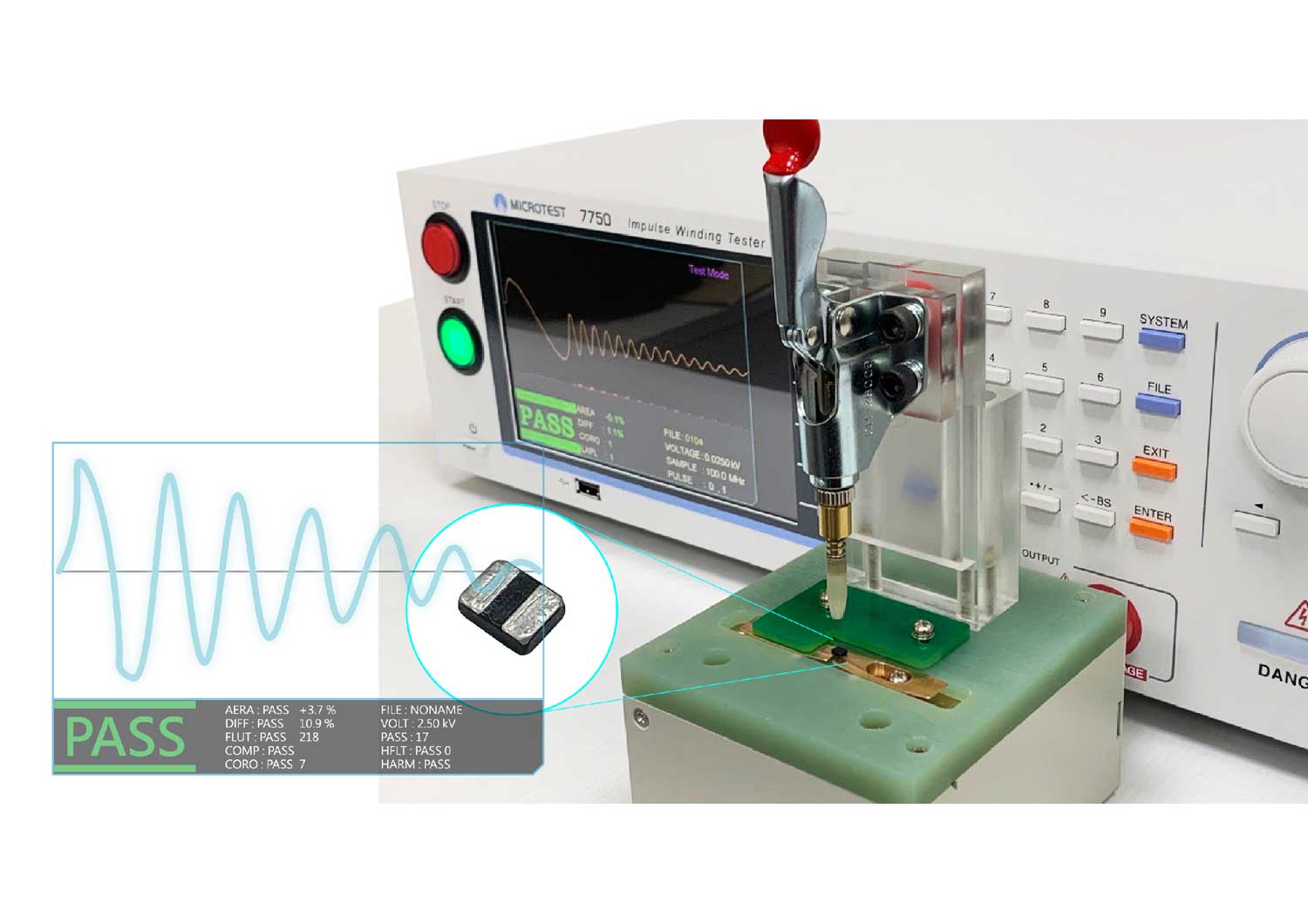
For testing small components, the optional 7750-1S tester comes with the FX-IM0001 four-wire SMD component testing fixture. It features voltage compensation to minimize voltage errors caused by wiring and equivalent inductance, ensuring accurate quality control for products with small inductance.
Features
- Lowest Inductance (≥0.1μH)
- High voltage calibration
- programmable impulse voltage
- 200MHz/9bit High Impulse Test Sampling Rate
- Total Area Comparison<
- Differential Area Comparison
- Corona Comparison
- LAPLACIAN Comparison
- Voltage Compensation Function
- The meaning of the Corona, Flutter and Laplacian comparison:
Corona comparison counts corona occurrence to detect discharge.
Flutter comparison measures the total area of high-frequency waveform fluctuations to quantify waveform tremors.
Laplacian comparison sums the second derivative of the waveform (the rate of change of the voltage change rate) to determine how much the high-frequency wave is fluttering. - Is the HV output grounded?
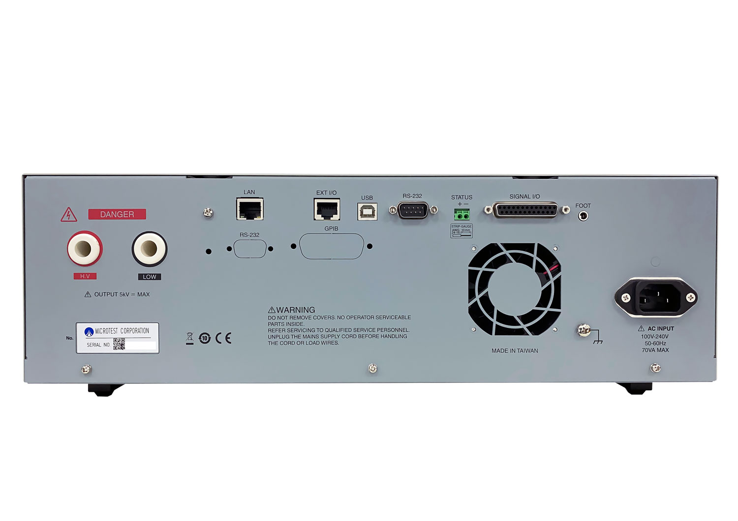
Yes, the negative side of the output is grounded. - About the setup:
The goal of all comparison modes is to measure discharge in different ways. There is no shared standard. The settings are usually found by trial and error.
What I would recommend is to go through the following process:
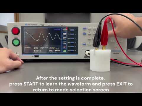
- Finish the initial waveform learning and standard setting.
- Test at least 10-50 of the products that is on the production line and check the total yield of the batch.
- If the yield is too low, the standard is too strict. Lower the test voltage or the pass limit.
- If the yield is too high and you want stricter control, consider raising the pass limit or increasing the test level.
- Finish the initial waveform learning and standard setting.
Product Images

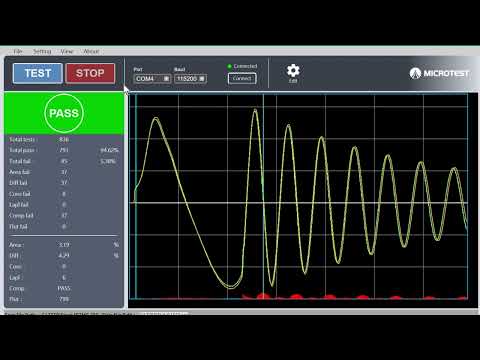
Total Area comparison

Differential area comparison

Corona comparison

COMP Comparison


 Microtest Impulse Specification 7750