


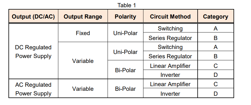
DC or AC regulated power supplies (hereinafter called ‘power supply’) can be classified into eight types and four categories in accordance with the output source (DC or AC), output range, polarity or circuit method as shown in Table 1.
In this white paper, we look at four characteristics associated with the power supply’s specification: line regulation, load regulation, transient response and ripple noise. We also discuss how to determine the ability of the power supply by these four characteristics. Note: This white paper refers to the constant voltage characteristics based on an AC line input.
1. Line Regulation
Firstly, here’s how electricity gets to your power supply: 1) Power plants generate electricity. 2) Electricity travels via a power grid. 3) Electricity is distributed by a circuit breaker at your home or office. The circuit breaker is connected to each of electrical outlets by wiring. 4) Finally, electricity travels through these wires to the outlets where your power supply is plugged in.
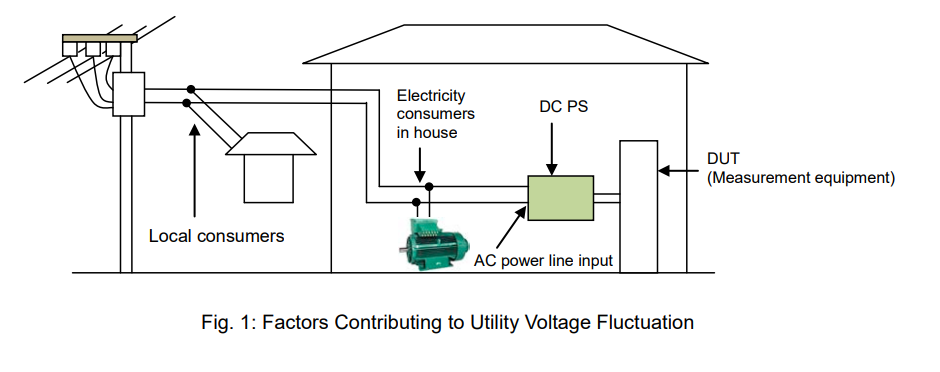
See Figure 1 below: if some electricity consumers on the same distribution line consume large electric power, the utility voltage drops, and vice versa, if they consume less power, the utility voltage rises. A good power supply can keep its output voltage stable despite the utility AC voltage fluctuation.
Line regulation is changed in power supply output voltage due to variation of input line voltage. It is expressed as an actual change value in the output voltage relative to the ±10% change in the input line voltage (The standard input line voltage is: 120 Vac in U.S.A and 100 Vac in Japan). For industrial power supplies, the change in the input line voltage may be defined as ±15%. The input voltage at which the power supply is designed to work (such as the standard voltage ±10% or ±15% as above) is the rated input voltage.
The performance specification for the power supply is ensured within the rated input voltage. Some power supplies define a wide rated input voltage range under the specific line regulation. In general, a good power supply has small line regulation but it is difficult to develop.
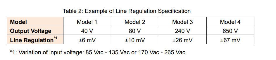
*1: Variation of input voltage: 85 Vac – 135 Vac or 170 Vac – 265 Vac
2. Load Regulation
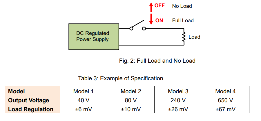
A load on an electrical system is any device, part or portion of a circuit to which power is drawn from a power supply. So, how do you find which power supply can deliver enough current to your load? To choose an appropriate power supply to your load, check the rated output current, maximum load current that a power supply can provide, specified on its product data sheet. Furthermore, in fact the load current is affected by the load variation.
If the output voltage of your power supply significantly changes with the load variation: ● Your load may be damaged due to an unstable output voltage.
● Test data reliability or test reproducibility cannot be ensured due to the test voltage variation. Load regulation measures how much the output voltage is affected by the load variation from 0 to 100% (no load to full load).
A good power supply has small load regulation.
3. Transient Response
For example, the load regulation can be measured by the formula:
‘output voltage value after keeping a no-load state for 10 seconds’ – ‘output voltage value after keeping a full-load state for 10 seconds’.
This formula indicates that: ‘No-load voltage under a stable output voltage’ – ‘Full-load voltage’. The output voltage dynamically fluctuates while in the load current variation such as when a load is switched from no-load state to full-load state and vice versa. Transient response is the response characteristic how a power supply responds to a sudden load variation, that is, the time until an output voltage reaches a steady-state.
Note: Some power supplies define a no-load voltage as 10-plus % of a full-load voltage.
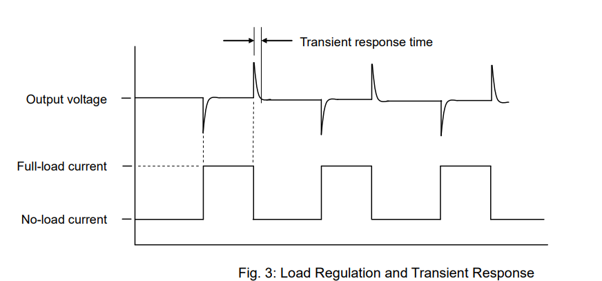
It is important how fast a power supply returns back to a steady-state. In other words, a good power supply has an excellent transient response time.
A power supply should provide a faster enough transient response to a load, otherwise a load current fluctuates before an output voltage returns to a steady-state and an output voltage becomes unstable.
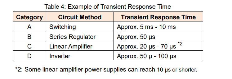
See Table 4 for the reference value of the transient response time for each category of power supply.
4. Ripple Noise
A power supply consists of several components such as a power electronics circuit that converts a utility AC to a stable DC/AC output. To provide a stable voltage output, a power supply performs a negative feedback control; however ripple noise can be prevalent during this negative feedback operation. Figure 4 shows the typical waveform for ripple & noise generated from a power supply.
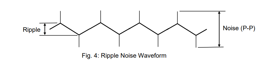
If your power supply generates a ripple noise, it will be superimposed on your DUT’s output voltage.
Especially with a high ripple noise, the following malfunctions may occur to your DUT:
A) If your DUT has a digital circuit:
● An input voltage for your DUT exceeds its threshold level and it may cause a malfunction on the digital circuit of your DUT.
B) If your DUT has an analogue circuit:
● Ripple noise is superimposed on your DUT’s output and it may reduce the quality of your DUT’s analogue signal.
Ideally, a good power supply has little ripple. In practice, however, you will purchase a power supply within a reasonably low-price range unless above malfunctions have been discovered. So, you may need to reduce the ripple noise depending on your power supply in use. If you want to know how to reduce the ripple noise, read the appendix below.
The higher the rated output voltage, the higher the ripple noise is provided by the power supply. Table 5 shows the typical ripple noise value according to the power supply category. Some power supplies may give the rms value and peak-to-peak (P-P) value of the ripple noise.
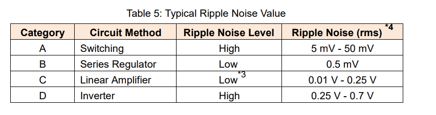
*3: If a linear-amplifier power supply incorporates a switching regulator, a ripple noise may increase. A lower ripple noise may be achieved by high-speed bipolar DC power supply.
*4: Measurement frequency bandwidth: 10 Hz to 1 MHz
Appendix: How to Reduce Ripple Noise from Power Supply
1. How to Reduce Ripple Noise
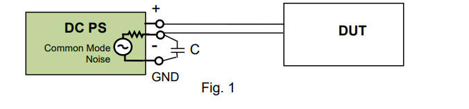
1) Connect negative output terminal of power supply to ground
Connect a negative output terminal and a ground terminal to minimize a high frequency common mode noise generated between both terminals. Figure 1 shows that a capacitor is placed between both terminals. If your DUT is accepted, connect both terminals by a conducting wire.
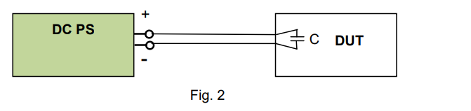
2) Place capacitor at feeding point of DUT
Place a capacitor (approx. 0.1 µF – 1 µF) at a feeding point of your DUT to reduce a high frequency common mode noise. This method is effective when the wiring distance from a power supply to a DUT is long.
2. Precautions for Ripple Noise Measurement
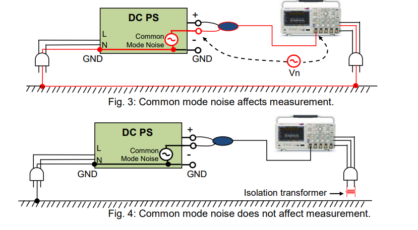
When an rms value is measured by a true rms meter or a noise is measured by an oscilloscope, place an isolation transformer between the true rms meter or oscilloscope and the power source line as shown in Figure 4. The isolation transformer eliminates a high frequency common mode noise to minimize measurement errors.
As shown by the red line in Figure 3, the common mode noise current is generated from the DC power supply and passes through the ground and returns to the power supply line. If the current flows through the probe cable jacket of the oscilloscope, the voltage Vn is generated and added to the measurement. The isolation transformer can eliminate this voltage Vn.
Products Mentioned In This Article: