


A regulated DC power supply (referred as DC power supply) is an electrical device to convert AC into a constant DC. Its function is to maintain a constant output voltage, however, unfortunately even if you use an intelligent DC power supply, improper wiring can mess up a whole system operation or performance.
In this white paper, we explain the best practices for connecting a power cable and load cable to the DC power supply (assuming that the DC power supply operates in constant voltage mode). It can help you learn more about typical wiring problems in an electrical system and how to avoid them.
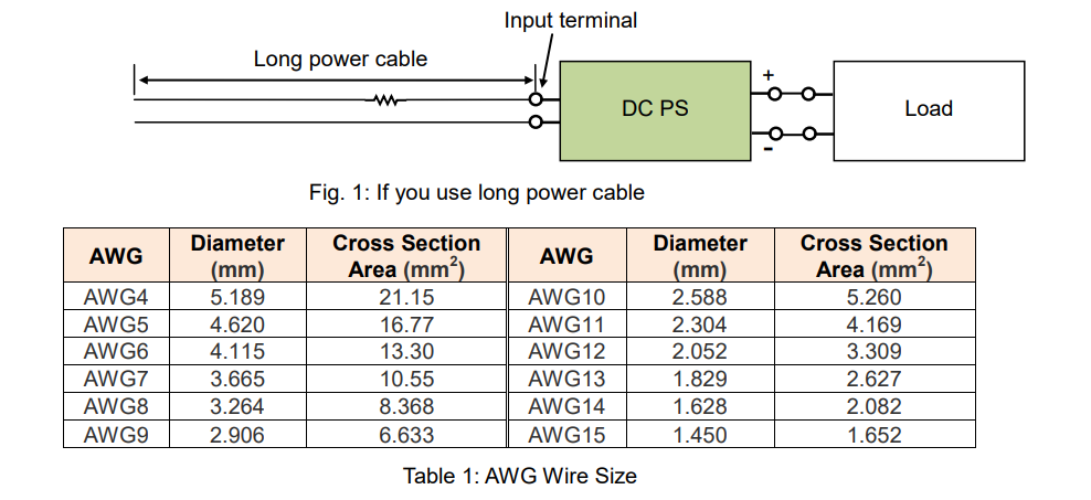
1. If you use long power cable
A power cable is a fundamental component that transmits electric power to devices in any electrical system. Basically, as the more power is produced by a DC power supply, the more current flows through a power cable.
Also, a power cable resistance is proportional to its length. That is, an AC-line input voltage can drop over a long power cable. As the more power is produced by a DC power supply, the more AC-line input voltage drops.
If an AC-line input voltage falls to a minimum rated input voltage of a DC power supply, an output voltage can decrease or fluctuate. Even worse, an input voltage drop protection may activate to turn the output off.
Before you have such issues, check whether an AC-line input voltage meets a rated input voltage first and then take the following preventive actions, if needed:
1) Use a power cable as short as possible. If a cable length becomes half, an input voltage drop becomes half, or
2) Use a power cable as thick as possible. If a cross section area of a power cable is doubled, an input voltage drop becomes half, or
3) Check for a loose power cable connection and tighten it when necessary.
2. If you use long load cable
With a long load cable, a load current can increase and then a load voltage drops. To compensate for the voltage drops, some DC power supplies feature a remote sensing function. This section explains the different effects between using and not using the remote sensing function.
2-1 Using remote sensing function
The wire inductance is proportional to the length of the load cable. When the load current (‘IL’) is pulsating and rapidly fluctuates, the load voltage (‘VL’) also oscillates in response to IL (See Figure 3).
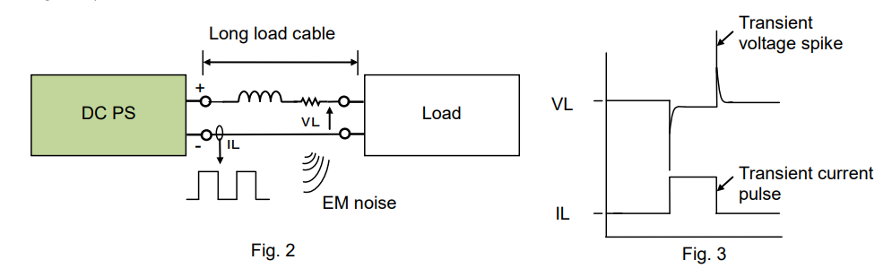
With the long load cable, the entire system may not work as expected because;
The transient load voltages may cause the malfunction to the load.
The transient cable current may become an EM noise source.
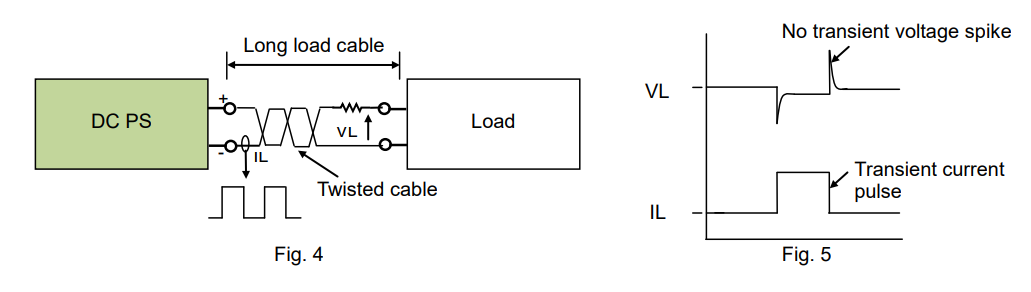
To avoid them;
1. Twist the positive and negative load cables together as shown in Figure 4 or 2. Place them as close as possible.
The twisted pair cable can reduce the effect of the EM noise and then reduce the transient voltage change (See Figure 5).
With or without above actions taken, if the transient voltages still persist, place an electrolytic capacitor (‘C’) as shown in Figure 6 below. The capacitor can prevent the transient current from superimposed on IL. For faster transient currents, place a ceramic capacitor in parallel with C. As shown in Figure 7 below, IL has no rapid change, and consequently VL is regulated.
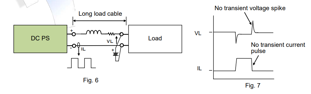
*Note: All figures given in this section illustrate the equivalent circuits of the system. The wiring diagrams are simplified that the resistance and inductance components are illustrated on the positive terminals only.
2-2 Not using remote sensing function
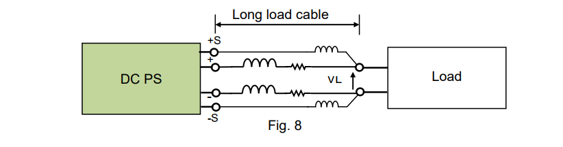
See Figure 8 for the equivalent circuit of the remote sensing connection. All cables consist of resistance and inductance components and the voltage will drop across these components. The remote sensing function can compensate for this voltage drop and keep the load voltage (‘VL’) stable within a set voltage. However, sometimes it does not work that the cable inductance may induce the oscillation.
To avoid the oscillation;
1) Twist the positive and negative load cables together (or place them as close as possible) to reduce the cable inductance.
2) Twist the positive and negative sensing cables together or use a shielded twisted pair cable to reduce the cable noise and inductance.
For further improvement;
3) Place a capacitor ‘C1’ and ‘C2’ across each positive terminals and negative terminals as shown in Figure 9. It allows the DC power supply to make a slow response to the load voltage fluctuations at a high-frequency, but the load voltage may become unstable. To fix it, place an electrolytic capacitor (‘C3’) on the load line (Read Section 2-1).
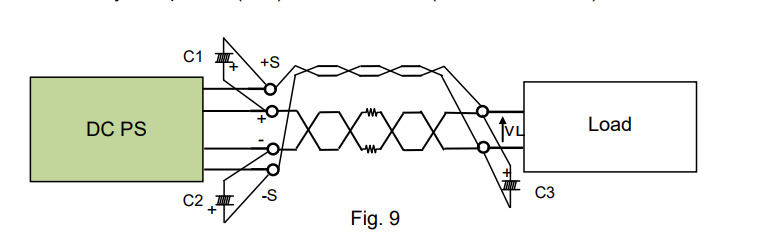
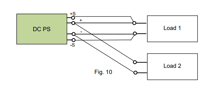
Figure 10 and 11 show the multiple load connection examples. As you can see, the sensing connection should be made to only one unit of load.
In Figure 10, assuming that the wire resistance and cable length are the same in Load 1 and Load 2, then the similar load voltage can be achieved for both loads. Also note that, if Load 2 is in a light-load state, the voltage drop can be offset by the sensing function for Load 1, but this compensation voltage may be directly added to Load 2.
In Figure 11, the load cable connected between Load 1 and Load 2 are thicker and shorter to minimize the wire resistance. This is especially helpful in obtaining a stable voltage when Load 2 is in a light-load state.
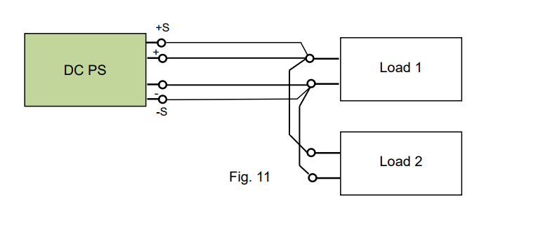
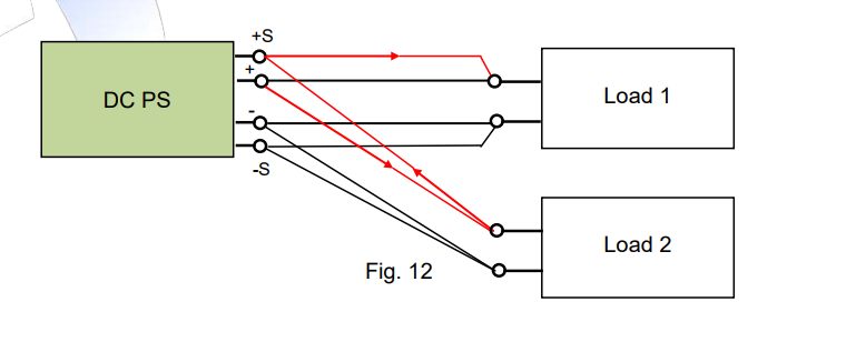
Figure 12 below shows the incorrect example that the sensing connection is made to each load. In such connection, the following may happen;
First, the load current through the load cable depends on each load state, and the voltage across each load depends on the load current. If using loads with different capacity, the load voltage balance cannot be maintained and the potential difference may be applied between the loads. With the potential difference, the current may flow from the high to low voltage via the sensing wiring. For example, see the red arrows in Figure 12 (positive side example only). If this current is high enough, the sensing cable may burn out.
Caution: Always perform a single sensing connection on multiple loads for safety.
Part 1 has so far focused on the wiring effects on the DC power supply.
Next, Part 2 will continue how the DC power supply depends on load conditions. Please also read Part 2 to gain further understanding or insights.
Products Mentioned In This Article:
Kikusui DC Power Supplies please see HERE