


1. Test Condition
: Conduct the vibration testing on the automotive wiring harness connector under supplied at 12 VDC/1 A.
2. Test Criteria: If the resistance of the wiring harness connector exceeds 7.0 Ω for more than 1 microsecond (us),
it defines an electrical discontinuity.
3. Test Circuit:
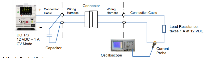
4. How to Conduct Test
• Calculate the resistance of the wiring harness connector based on the current change using Ohm’s law (measure the current and the time interval with an oscilloscope); E.g. If the current changes from 1.0 A to 0.63 A; it would be approx. 7.0 Ω (excluding the resistance of the connection cables).
• If the connection cables are too long from the DC power supply to the wiring harnesses, place a capacitor at their connecting point to reduce the cable’s inductance.
• Operate the DC power supply in constant voltage (CV) mode. Since the voltage is constant, the current depends on the connector’s contact resistance and the load resistance. So, the connector’s contact resistance can be accurately measured.
• The resistance calculation accuracy is affected by the inductance of the wiring harnesses and the connection cables. To minimize the induction effect, make them into a twisted pair and as short as possible.
• Use a non-inductive resistance for the load resistance (Do not use an electronic load instead, otherwise the current cannot be accurately measured.)
• We recommend you to use a current probe for the current waveform observation. If connecting a resistor to observe the waveform, you may not obtain an accurate measurement especially if the voltage becomes lower due to noise generated from the connector.
Products Mentioned In This Article:
- PMX Series please see HERE