


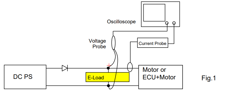
There are two methods to absorb motor’s regenerative current; Voltage Clipping Method and Bleeder Method. The following describes the characteristics, functions and precaution for the methods. Fig.1 illustrates the typical test system.
1. Voltage Clipping Method
This method is to set the electronic load in CV mode to clip the motor’s regenerative current. If the regenerative current is not fully followed, overshoot may occur even with this method. The overshoot occurs depending on the relationship between the rise time of regenerative current and CV switching time of electronic load:
-The faster the CV switching time is, the more voltage can be saved.
-Motor impedance determines the rise time of regenerative current. The larger the impedance is, the slower the rise time of regenerative current becomes.
This allows CV switching to perform properly, and the overshoot can be suppressed.
1-1 Response Time for CV Mode with Typical Electronic Load
The following are the response time for CV mode with PLZ205W. In PLZ-5W Series, you can choose two modes for CV switching. Fig.2 is for Fast mode, Fig.3 is for Normal mode. Measurement Condition:
– 15V is set to PLZ205W for the CV setting.
– When approx. 12V is applied to PLZ205W, PBZ60-6.7 applies rapid constant current (approx.30μs).
The yellow line shows when the voltage was clipped: Fast Mode: approx. 300μs Normal Mode: approx. 3ms
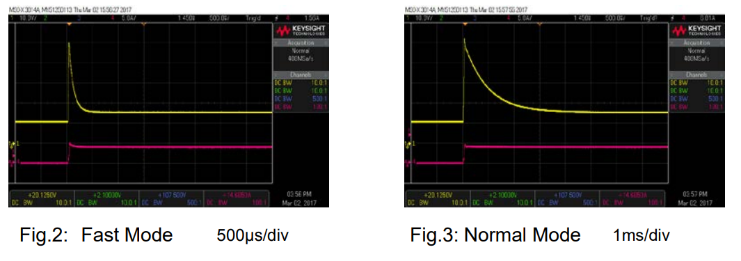
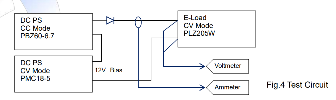
In Fig.2 and Fig.3, the overshoot voltage was much high. It is because PBZ60-6.7 applied 60V and the rise time of current is fast (approx. 30μs). Fig.4 illustrates the test circuit.
1-2 Precaution in use
Since impedance varies by motor, pre-test is recommended to check whether: – Overshoot is clipped until it meets your satisfaction.
– Oscillation occurs depending on the combination and compatibility between the motor inductance or load cable inductance and electric load.
2. Bleeder Method
This method is to set the electronic load in CC mode to always flow the higher current than regenerative current into the electronic load. When the regenerative current flows, the voltage of electronic load becomes higher than the power supply voltage. In such condition, the power supply current is cut off and the regenerative current flows into the electronic load to clip the regenerative voltage.
To drive the motor:
– Power supply should have the output current capacity for ‘motor drive’ + ‘regenerative current’. – At least the same amount of regenerative current should be always flowed into electronic load. Fig. 5 shows the result to clip the regenerative current with this method. This test circuit is shown in Fig.1.
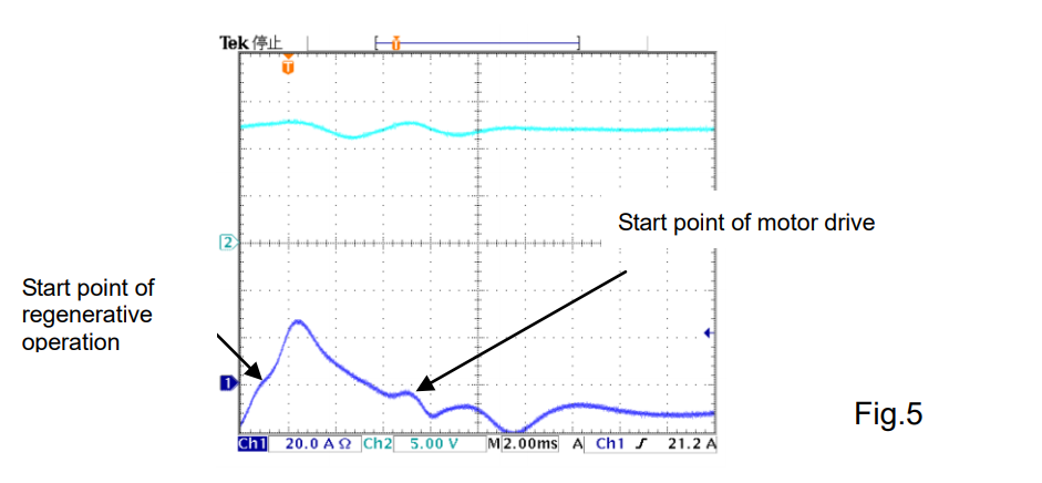
The merit of this method is that you can clip the voltage without overshoot. On the other hand, the current of electronic load for the regenerative current is continually being wasted. Therefore, please be noted that the system consumes quite a large power.
Products Mentioned In This Article:
- Kikusui Electronic Loads please see HERE