


The switch on/off testing can be performed with a combination of DC power supply and electronic load (See Figure 1). To successfully conduct the testing, it is important to know that the current flow through the switch varies by the electronic load specifications or settings. Especially during the life testing, you should be aware that it may affect the lifetime of test switch.
This white paper shares the measurement results using our different electronic loads and helps you understand how to choose or set an electronic load for your switch testing system.
1. Switch Testing System Configuration and Test Conditions
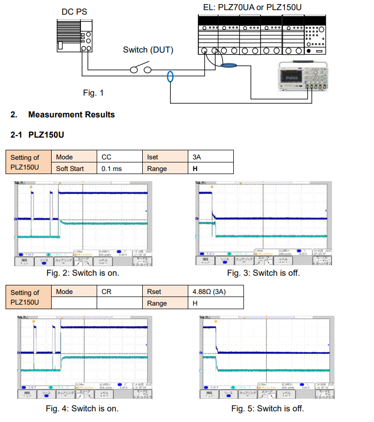
Figure 1 shows the system configuration diagram for the switch on/off testing.
Test Conditions: Set DC voltage to 14.6 V by DC power supply. Set PLZ150U or PLZ70UA in CC or CR mode.
3. Important Points for Switch Testing System
Consider the following points when preparing the testing system;
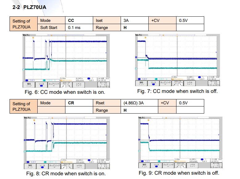
1) Almost no current is supplied during the chattering at switch-on (See Fig. 2, 4, 6 and 8). *1
2) Set Soft Start to 0.1 ms to start the current flowing as soon as possible.
3) The magnitude of current differs in CC mode and CR mode at switch-off. Higher current can flow in CC mode (See Fig. 3, 5, 7 and 9).
4) Connecting an electrolytic capacitor in parallel with the electronic load input is also effective to simulate the start-up inrush current (switch-on surge). With the capacitor, very little voltage will be applied on the both side of the switch at switch-off.
5) Set the CV value (+CV mode) if using 0 V input operating voltage type of PLZ Series, such as PLZ70UA, PLZ164WA or PLZ664WA.
*If the power supply’s output is turned off first, the electronic load may cause an alarm. Turn off the electronic load first and then turn the power supply’s output off.
6) Overcurrent testing can be also performed in the same system; Use an electronic load whose capacity is large enough.
Under the above test conditions, PLZ150U can provide the better results than PLZ70UA.
*1: The Soft Start function is gradual starting up of an electronic load to avoid the overshoots of current. While the short-pulse voltage is first applied to an electronic load during the chattering, the Soft Start will minimize large startup currents from flowing. It delays the current start-up time for approx. 0.1 – 0.2 s.
Products Mentioned In This Article:
- Kikusui Electronic Loads please see HERE